Convoluted Neural Network Dice Roller
Code:
Date:
April ’25 – May ‘25
Why:
I needed to choose a topic for my final project for my machine learning course at CSULB.
What:
While I was in my last semester at Fullerton College I was trying to think of a way that could generate truly random numbers. I saw some devices that you could buy on Amazon that were about $90 and they were a USB that used heat for this. I also knew that cosmic background radiation and also the decay of certain radioactive isotopes were also used to generate random numbers. The one I wanted to make was way more simple than that. I would be reluctant to even call it truly random because there could be a flaw with a physical machine that leads to people being able to predict outcomes, but this was for a class and was just something fun that I wanted to do. I was not about to be ensuring that messages were cryptographically secure with this thing, and as you will see it was plenty flawed.
This idea was supposed to be a dice roller that was fully automated. It would roll the die, and then it somehow determine what the number on the die was, and then it would either record the number or report back to the user what the number was. I was sure that there was some way to do it but it sounded involved and truthfully I kind of forgot about it.
Then during lecture one day we started talking about edge detection in images. There was something very interesting to me about this. Over the course of the next couple of weeks we started talking about convoluted neural networks (CNNs), and that is when I remembered the idea for the dice roller from three years ago. Three years before that would have been a considerably challenging project. I had not done any embedded systems programming at that point. I started to get the feeling that the dice roller was something that I could make. I asked our professor, Dr. Ghasemkhani, if I could do this as my final project and he said yes. (I was fortunate enough to have the opportunity to present the project to the class as extra credit, and I will include a link to that presentation in the resources below.)
*****
The first thing I did was tried to find some video online of somebody the MNIST dataset and training a CNN in PyTorch. MNIST stands for Modified National Institute of Standards and Technology and it is a database that consists of the handwritten digits zero through nine. There are 60,000 training images and 10,000 testing images within the set. I can’t take any credit for the CNN that was used in this project. I watched a video by the YouTuber NeuralNine where he gave a tutorial on how to do exactly what I was trying to do. What he did not do in that tutorial was take any of his own pictures, and then format it the way MNIST pictures are formatted (28×28 pixels in grayscale). He did mention that this was something that could be done.
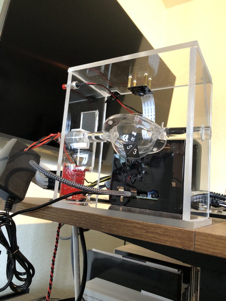
So far it did not seem too bad. I had a Raspberry Pi NoIR V2 camera at home. I had also recently purchased an ElectroCookie case for a Raspberry Pi 4B and had not had not had a reason to put it together yet so this was good. The case has these little slots where you can slide a ribbon cable through.
One of the first challenges for this project was getting the camera plugged in. I’m not joking. I immediately broke the little flimsy black plastic clip used to secure the ribbon cable in place. So hot glue it was. Initially I tried using the latest release of Ubuntu desktop for this project. That was the plan with ESRA was to use the Ubuntu version until there was money, or a real need, for a dedicated laptop. Then you could switch to the laptop that had Ubuntu on it and members would already have experience with Linux.
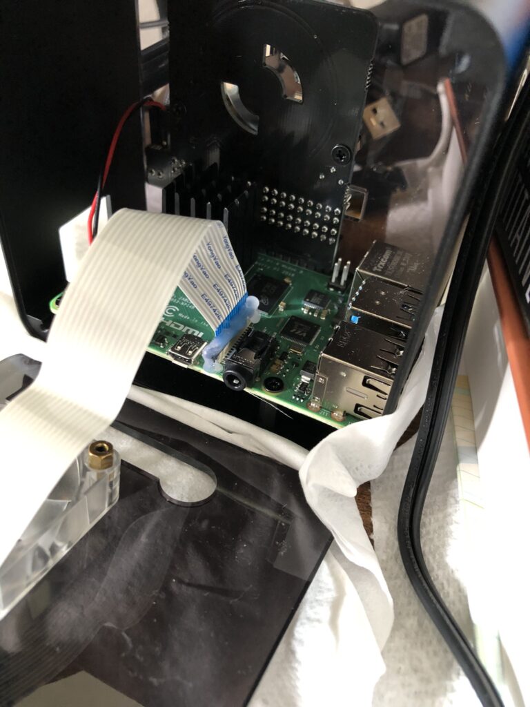
Anyway, using the camera did not go very well. I can remember one Saturday I spent about eight hours trying to figure this out with little to show for. About halfway into that time I started to use ChatGPT for advice on how to troubleshoot this camera on this operating system. (I kept receiving errors about the I2C bus.) It didn’t go very well. ChatGPT kept saying things like, “You’re so close. Just this one little additional thing,” for four hours, and then I ran out of data. I had not been using ChatGPT very long at the time, and looking back on that day it is pretty funny, but I was pretty annoyed. I ended up installing Rasbian, and after doing some Googling (remember, because I ran out of data), I was able to get the camera taking pictures. I was also relieved that I had not completely messed up the ribbon cable for the camera. I could tell through some terminal inputs that the camera was being detected, but up until then I was still concerned that maybe the connection was not lining up for all the pins.
Shortly after this I followed tutorial by NeuralNine and wrote the code in the Thonny IDE to see if I could get everything working. I was using an 8Gb RAM version of the Raspberry Pi 4B and I can remember wondering how long would it take to train the model. If I remember correctly it took about 25 minutes. Unfortunately, I ended up needing to train it twice because I forgot to look up how to save the model once it had been trained. Of course I realized this on epoch 9 of 10 so I figured I would just let it finish and see what happened.
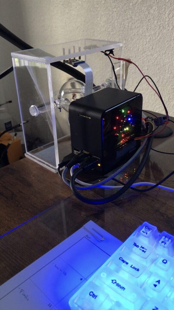
The second time I succeeded in saving the model, and was able to use it again after that. This was starting to get cool. I still needed to create some type of stand for the camera to go on. I had seen online where you could buy these acrylic hemispheres. The plan was to house the die within these two hemispheres, and then I got thinking that it would be really cool if I could make the entire setup acrylic. Initially I had purchased wooden dowels but I replaced those with acrylic dowels. I also bought tiny jeweler files to create a slot in the dowels that the two rims of the hemispheres could slide into. Next, I would put a M3 screw through dowel and flared edges, and put a nut on the other side and call it good. If only it were that easy. Creating those slots proved to be very challenging and I almost ended up using the wooden dowels instead.
Even after I had made the dowels flat where the nut and screw would go, and had finally succeeded in getting the hardware installed, the results were not very reassuring everything still felt wobbly. I ended up using clear epoxy over the top of the screw and the slot that I had created. While I was doing the last slot something interesting happened: the top half of the slot broke off! Are you kidding me? I remembered from the epoxy instructions that the set time was something like 15 minutes. I ended up retrieving the dowel piece and pinching everything in place, with a gloved hand, and just waited until it set trying not to inhale the epoxy fumes. Surprisingly, it actually turned out okay. My goal was to do some experimenting with the motor to see what time would be necessary to bring the hemisphere to the same resting place after each run. This was important because even though the two hemispheres were transparent if they stopped where the flared edge was facing the camera, then you would not get a good picture. At this point though I had introduced so much error into the system that this was not going to happen. There were more errors to come too.
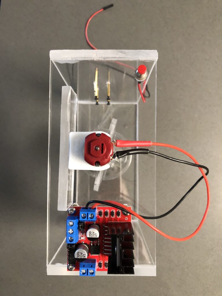
I had purchased a whole bunch of brushless DC motors as a part of a soldering workshop that I was planning for ESRA. I never did get around to doing that, but I had a whole bunch of these motors at home. I ended up drilling a hole in the dowel and putting a small amount of clear epoxy on the shaft of the motor. Next, I inserted the motor shaft into the dowel, but I was very careful not to push the motor in too far and get any epoxy on any part other than the shaft. The motor seemed mostly straight. The motors came with these small plastic holders that they could rest in and I was hoping that these would be strong enough to keep the motor in place (it was). However they could not just remain suspended mid-air so I cut an extra strip of acrylic that would act as a sort of shelf for the motor. My thought was that the motor mount would sit nicely on this shelf and that I would not need to do any more epoxying or anything crazy.
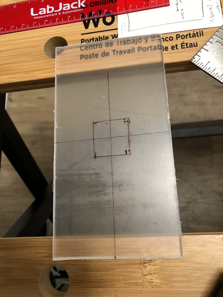
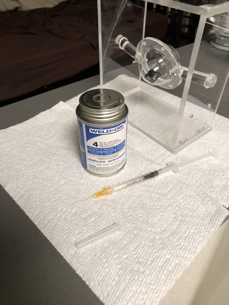
The rest of the assembly for the dicer roller went smoothly, but this motor shelf proved to be a a problem. I used WeldOn4 to connect all the acrylic pieces (after seeing how bad super glue caused the acrylic to “fog” on the igniter box for ESRA – I decided to look into how to make that not be a thing in the future). After I mounted the L298N motor driver board, camera, and push button (kind of) I decided to do some test runs. At this point I had written the main program that would receive a GPIO signal from the pushbutton, and then send and on signal to the motor driver board for half a second.
What I found is that the motor holder needed to have some freedom because if you held it down then it would not turn. However if it was left to turn without any restriction it would start to bounce and the dowel would fall out. I ended up using masking tape to keep it in place and this worked alright. There were bigger problems related to the model itself that were about to come up. Earlier when I said that the push button was kind of mounted – what I meant is that the 1/4” acrylic that I was using was too thick for it to be secured correctly. I am not sure how I missed that when I bought the push buttons but it happened. If you watch the video for this project on YouTube you can hear a loud snap when I push the button, and that is because it’s not mounted to the acrylic. That noise is just the back of the push button slamming into the surface.
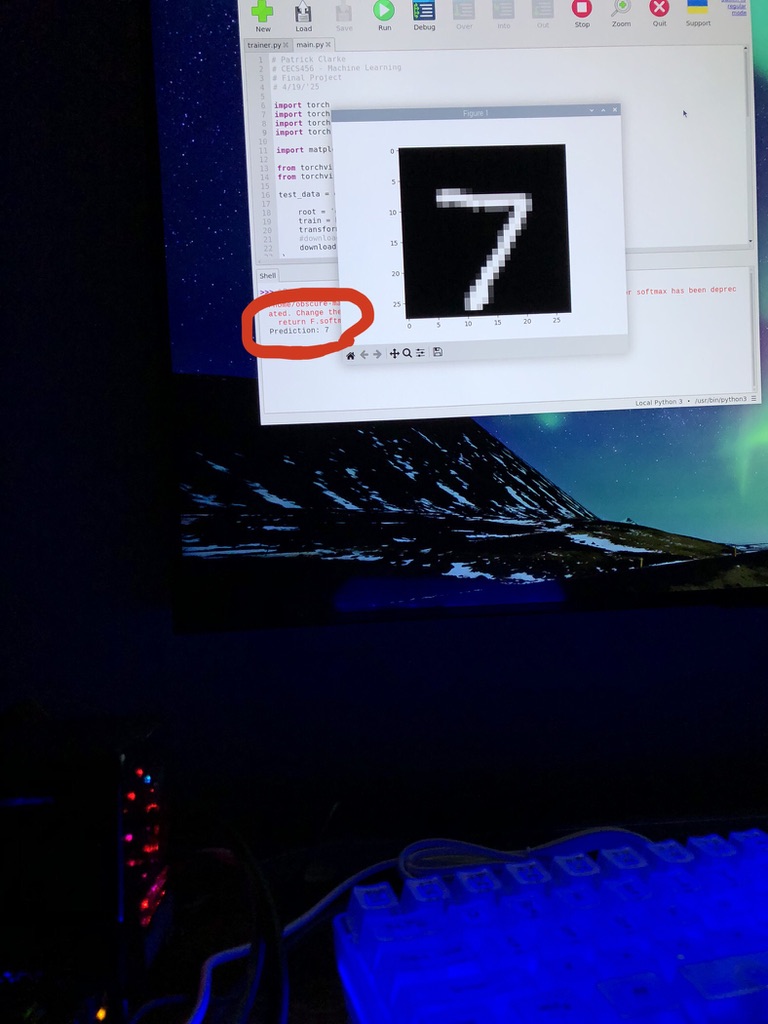
After everything had been mounted and was mostly staying in place it was time to actually start getting some pictures. I had captured some images earlier just by holding a die close to the camera, and when I saw that the model was correctly predicting the number on the die that was a really cool moment. The first dice that I purchased were white with black numbers, but after looking at the MNIST dataset more I realized that I would need to invert the colors for each picture. I figured if I could control for this on a physical level then I would not need to bother with additional code so I went ahead and bought black dice with white numbers.
Initially I wanted to use a ten sided die. However I did not really want to deal with the 10, which is not in the MNIST dataset, and I did not want to try and distinguish between a 6 and a 9. So I chose to do an 8 sided die instead. The plan was to have a set number of consecutive rolls, and have each roll correspond to a digits place. However, if the numbers on the die were 1-8 how would I get a 0? I decided that what would need to be done is that the model would make it’s prediction, and then for the digits place in the truly randomly generated number it would be decremented by one. Even though there are 0’s in the MNIST dataset there were none on the dice that I was using. In other words – each dice roll could be a digit within a base seven number system. So if you rolled a 1, 2, 3 then your number would be 012 in base seven, or a 9 in our base ten number system. I ended up not making it this far into the project, but that was the goal that I had.
The next step was to get everything focused. First I needed to adjust the physical lens of the camera so that the die became more sharply focused within the frame. After I had exhausted the physical variables I started working on the digital zoom. This presented a bit of a challenge. I found that the easiest thing for me to do was to capture images in the default resolution of the camera, then zoom in, then take that image and convert it to grayscale, and then turn it into a tensor. This took about four hours to do but it was complicated by many of the sources of error that I mentioned earlier. I think that if I had used smaller diameter hemispheres that I would have had more control over where the dice fell within the frame. However, the main thing that was screwing this all up is that on a software level the program would attempt to send a signal to the L298N motor controller board for the same amount of time, but because of all the issues with the dice roller that did not guarantee the same amount of rotations each time. It could get stuck and not spin at all and then capture an image. If that happened then I would have to move the dowel to get it un-stuck.
The biggest problem with this though was something that I did not think of until I started capturing images of the die, and that is the fact that all of the images within the MNIST dataset are of digits that are right side up. With my dice roller they could be any direction. There were instances, detailed in that powerpoint presentation, where I would roll an upside down two and the model would think that it was a three. If you rotated the image 180 degrees without modifying it in any other way then the model would correctly predict a two.
At this point I would not have had enough time to make the corrections as my project was due the following week. Up until then I had put off buying a 3D printer because I had not needed one before, but this project finally made me spring for one. I think that it would have eliminated many of the sources of error. It would not have fixed the rotation of the digits though. When I gave my presentation our professor asked me what the accuracy of the device was, and I felt like a fool because while the accuracy of the model itself was 98%, the accuracy of my dice roller was completely contingent on getting a good roll to begin with: one that was mostly in frame, with no hemisphere lip, and also right side up. His suggestion was that you could make the model more robust by adding rotated images into the training data. Then he mentioned that if you had a device like this and had the ability to take pictures, and automate that, then you could even add those to the training data, or even make a new dataset specifically for this application.
One final thing that I want to mention about this project is that I was really surprised by the amount of attention that this received on YouTube. I uploaded a short clip on Tuesday with the intention of only using it for the presentation. By Thursday it had over 1,600 views and one person had shared it. I had not added hashtags or anything like that. You may be thinking, “That’s not a lot,” and I agree – it is not, but it is more than double the amount of attention all of my avionics/rocketry projects received within the past two years combined. Which still is not saying a lot, but my point is that relatively speaking it was kind of a big deal, and I was really surprised that this had happened. I truthfully did not know that YouTube would even show your videos off in a way where other people could find them. One other thing was as I was walking back to my car on campus somebody told me that they liked my dice presentation!
Even if those things had not happened I would still have felt good about this project. It ended up not doing what I wanted it to, but it still was a lot of fun to work on. I might go back and try to fix the stand. Another improvement that I would add is having a 9V battery in place of the power supply, and then using a portable power bank to power the Raspberry Pi. It would also be cool to add a little screen on the front of the stand, and figure out a way to have this program run as soon as the Pi starts up. That way it would all be portable and you wouldn’t need a TV screen or anything like that. Fixing the training data to allow for more accurate predictions would also be necessary.
Resources:
1.) Slide show presentation for class:
2.) Demo video: