Beach Launch Team – EGSE
Code:
No code for this project.
Date:
June ’24 – August ‘24
Why:
The ALARA flight computer for BLT was being retired and was in need of a replacement.
What:
After the meeting I described in the CAN article I got to work on designing a switch box for what would become BLT’s new avionics system. The only switch box that I had seen before was created by Leo as part of a senior design project. He had graciously allowed BLT to use it during a portion of the water flow testing at Compton airport. (This was when the ALARAs were starting to die and we needed a way to actuate valves in case the flight computer decided to stop working completely.)
His system allowed a 5V signal from a power supply to be transmitted through switches to relays within a metal box that would then send a 24V supply voltage to the appropriate high powered object. Interestingly, the 5V signal and the 24V supply voltage came from the same power supply – meaning that it only ever plugged in at one place and was good to go. These relays were recommended by Mark Holthaus. Mark had mentioned during the meeting that MOSFETs tend to have a hard time at the FAR test site because of the heat.
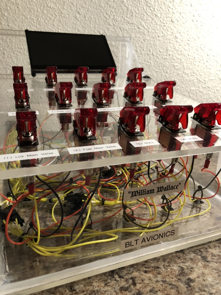
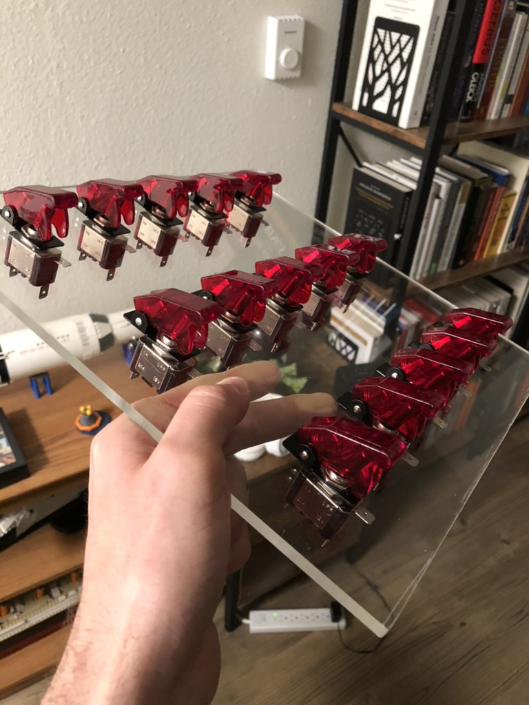
Taken together I decided that this would be a good place to begin. I did not have a 3D printer at the time, and I really liked the idea of having a box made from acrylic. I had this picture in my head of how cool some LEDs would look shining through the interior of the box. I chose some SPST switches from Amazon that I thought looked close enough to the one’s on Leo’s switch box.
I decided that I didn’t want the surface that the switches were all on to be flat, I wanted it angled for better visibility. I decided that the switch box should accommodate 15 switches total after talking with more senior members of the club. There would be 10 for valves, 2 for igniters, and 3 as extra.
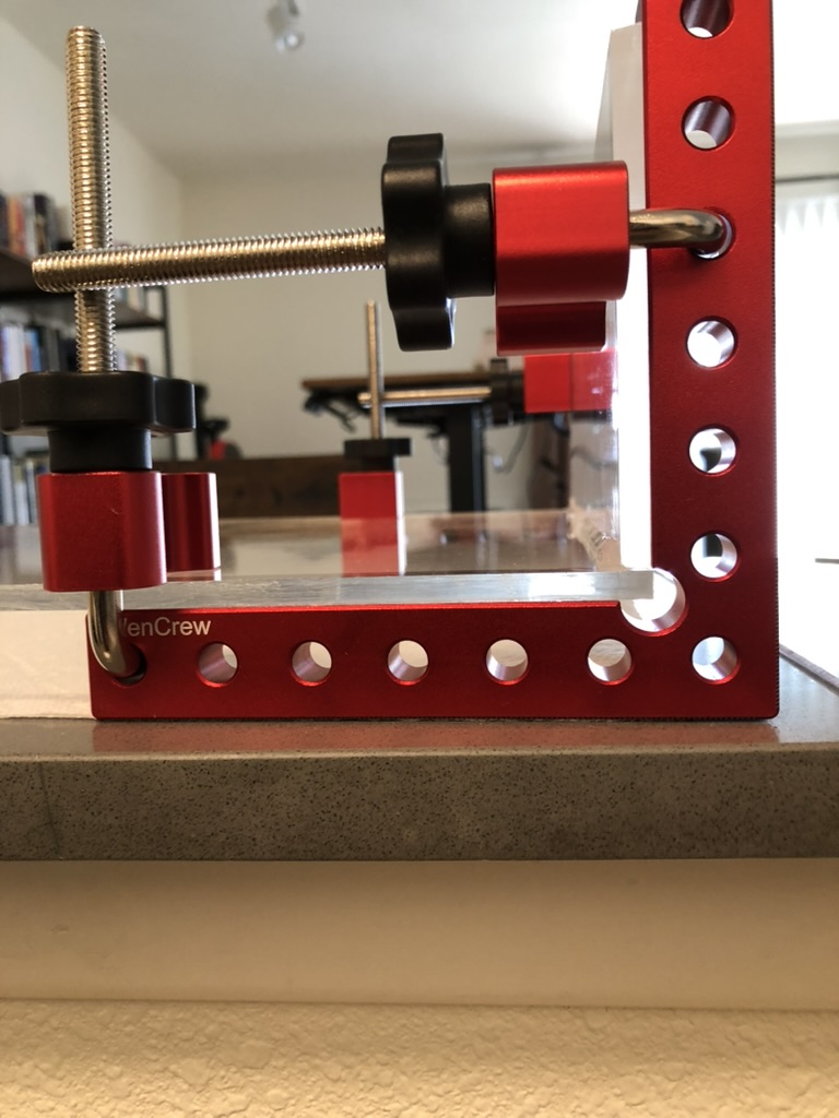
I also thought that it would be worth making room for a screen. This screen would have a Raspberry Pi mounted on the back of it and an antenna. The idea was that in the future somebody could observe telemetry on the screen, and when it was time to go retrieve the vehicle they could remove the screen, as well as portable power supply, and go find the launch vehicle if it had landed far away. It was supposed to be a way of making a portion of the GUI portable. The angles for the design were just chosen based on what I thought would look good if you were standing in front of it. I don’t have those original dimensions because it was very “back of the envelope”. I did like a little rough sketch and then made the cuts using a scoring knife and a portable work table in my kitchen.
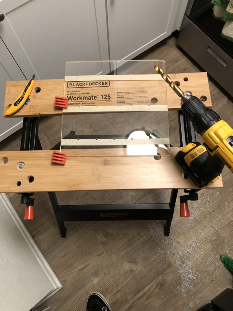
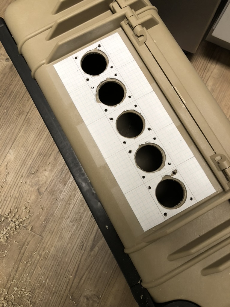
Next I made marks for where the holes should go on top of masking tape that I had laid out on what would become the top of the box. I drilled the holes and then went over all the edges with a dremel. I’m not sure why I used a dremel because I just kept melting acrylic over the top of whatever attachment I used. If I were to do this now I would use a file.
Then I got a little confused. I had done some research on how aquarium builders put tanks together. I bought some aquarium grade caulk that I saw mentioned repeatedly on this forum, and I also bought some corner clamps. If I were doing this today – I would have used WeldOn #4 and called it good, but I had never worked with acrylic before. Anyway, what I found was that the sealant by itself was nowhere near rigid enough to support the weight from the 1/4” thick acrylic sheets that I was using. I ended up removing the caulk, using super glue, which of course caused the acrylic to “fog”, and then for reasons I cannot begin to fathom now – put caulk back on. In case anyone reading this is wondering if switch boxes need to be water tight – the answer is no.
It was not long after this that I saw some older switch boxes in John Garvey’s garage. One of the best looking ones was just a toolbox that somebody had repurposed by putting the switches in where a tool holder would normally sit. I kicked myself when I saw that.
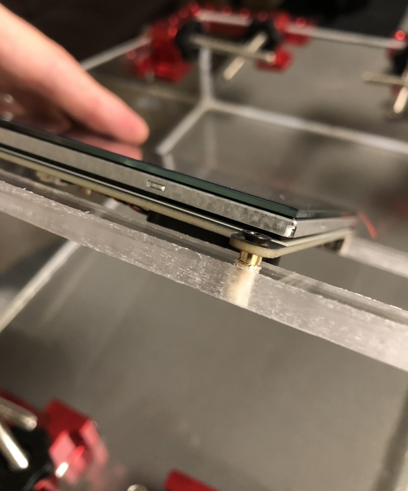
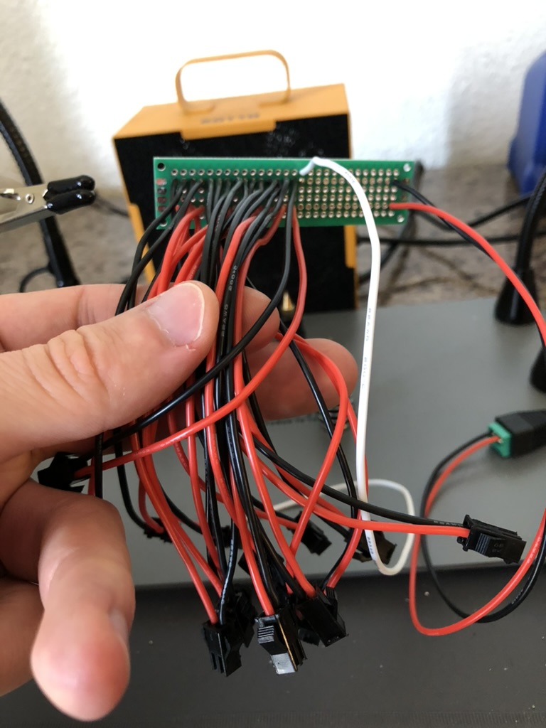
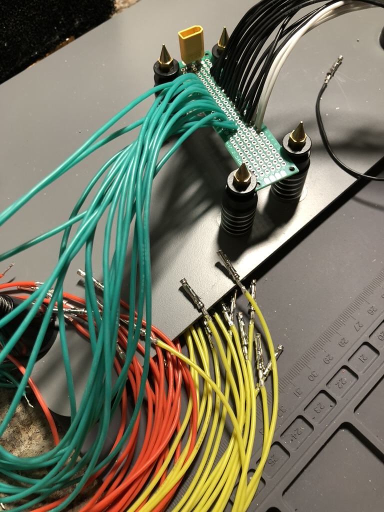
I had previously drilled 3mm holes into the base of the switch box, which had M2 heat inserts installed, and then I made sure that the standoffs lined up with the perfboard that I would be using to distribute power to each of the switches. I used a 5V 3A power supply for the signal voltage within this system.
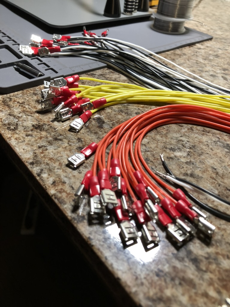
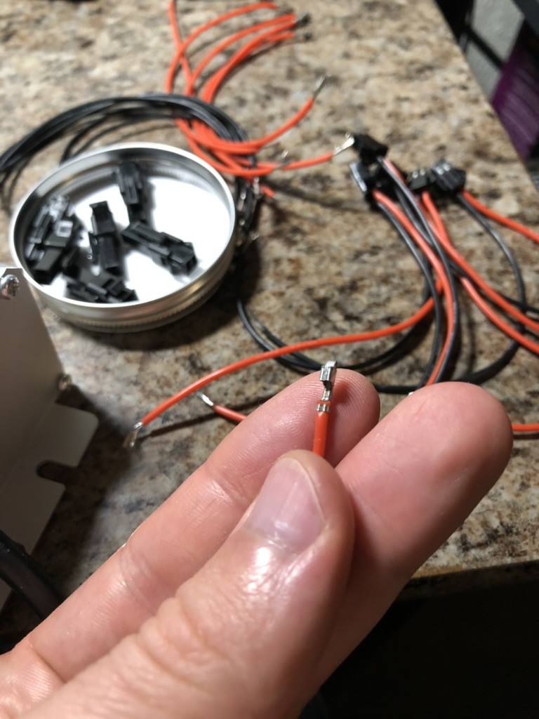
Next, I did a lot of crimping. I decided that these switches needed to have some type of small connector just in case somebody needed to remove the top of the box. The top of the box would not be connected to the switch box by any adhesive but instead held in place by zip ties and cable management pads. I looked around online and decided that the 2 pin JST SM connectors would be good. Using something like a two pin Deutsch would have been expensive, bulky, and overkill.
Looking back through my pictures during this time period this must have taken a while to do. I know I was busy with Garv’s project, and I was also in the lab a lot over the summer getting all the avionics equipment squared away and organized, but even then it seems to have taken a while to do all the harnessing for the switch box. I created a little slide so that the back of the box could be removed. This of course meant that no bulk head connector could be placed here. I ended up removing a corner of the slide, and then further back within the box I connected an L-shaped thing that I made out of acrylic to one of the walls. This “L” had a 37 cavity circular AMP bulkhead on it which is what was used to send signal voltage to the EGSE container. This was a little annoying to screw the connector into so later on I ended up filing away part of the slides that I had made for the rear cover.
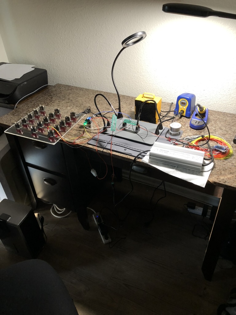
Around this time I started to do experiments with just the top of the switch box, relays, and cheap 24V solenoid valves. I figured this would be a good point to stop and ensure that everything was working correctly. After all if it did not work at short distances then why even bother with the cable work that was about to be done.
I made two big mistakes here the I ended up correcting later on in the ESRA design. First, I discovered that I could get the valve to actuate by just using one ground wire. On all the switches though I had harnessed up two ground wires because that is what was on the schematic that came with the switches: they had a ground wire going from the ground terminal to the load (the relay in this case), and a separate one going from that same terminal to the ground for the signal supply voltage. However, what I was finding is that if I just ran one ground wire to the relays then I could still actuate the valve. I could save money on cable this way too.
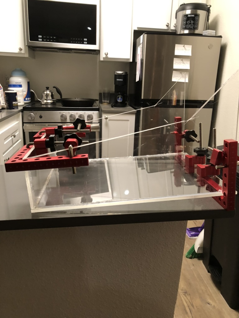
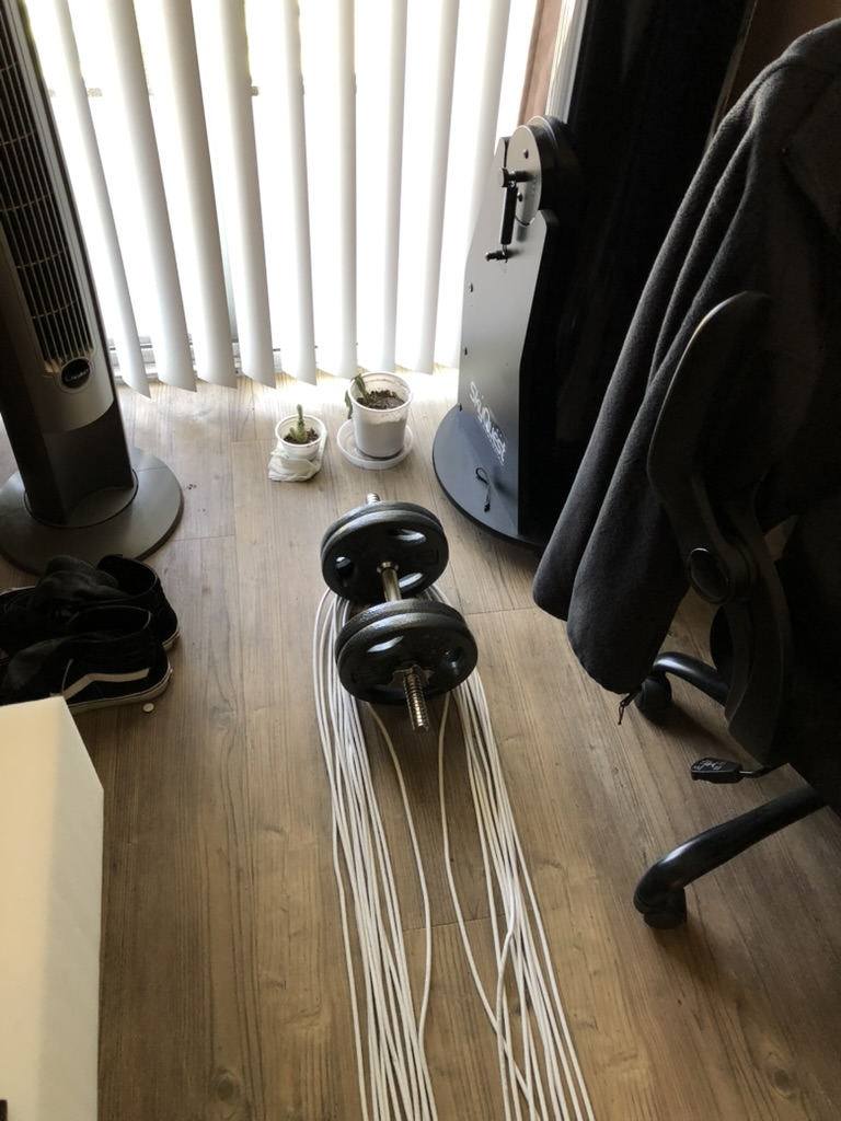
I removed one of the ground wires from each of the switches, and added one to the perfboard, and this was how I introduced inductive coupling into the BLT EGSE design. I had no clue what inductive coupling was at this time. The cable I used was CAT6 that had no shielding. I zip tied two 500’ lengths in my apartment by placing one small zip tie every four feet or so. I can remember thinking how great it was that I could use all 16 conductors and that nothing would be wasted.
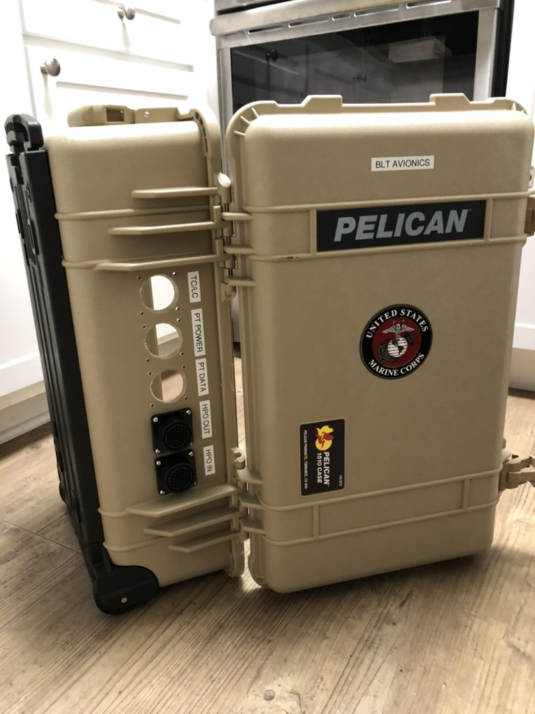
After this was done I shifted my focus to the actual EGSE container. For now it would only hold 24V relays, but in the future it would hopefully contain an improved version of ARALA. I did not know what size container to buy, but I knew the dimensions of the bulkhead connectors that I wanted to use, so I went based off that. I can remember looking at two sizes of Pelican cases. There was a larger one and a smaller one because it was more affordable. I picked the smaller one, and Amazon accidentally shipped the larger one! Nice.
The whole reason I chose a Pelican case was because when I was in the Marine Corps it seemed like everything valuable was housed in a case like this. Not only that but I tried to think of a time when I had ever seen one break during deployment or during a field op and I could not. I had also seen at least one hard start before, and I figured that if spending a little more money could provide some peace of mind, then it would be worth it. I paid for it out of pocket because I was still pretty green to hardware and I knew that there was a good chance that anything I created would fail, and I did not want to be the reason that the club could not afford propellant at the end of the year for launch. I also decided to put a Marine Corps sticker on the front of it. Before I forget one other piece of personal flair I added was naming the switch box “William Wallace” after the Scottish knight of independence. The joke was that he was going to liberate BLT from bad static fire attempts, like the one in June, which was an avionics failure due to the harnessing on ARALA.
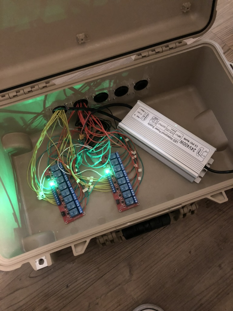
I made sure to put enough bulkhead connectors on the EGSE container so that it would be around for a long time. I wanted people to want to use it even after I was graduated. I did not want anyone to have to go through all that hard work again to figure out that this is the way to get rockets off the ground. So I made room for everything you would need for testing to include load cells and thermocouples (both of which were currently being handled by a separate piece of National Instruments equipment. This was made by Tryphena and was referred to as “The TryDaq”).
Figuring out the wiring for the relays did require watching a few YouTube videos. I can remember the strangest thing to me was having the COM pin connected to power. I had heard of “common ground” before but this was the other way around. I put a 24V 400W power supply within the EGSE container for the relays. I can remember looking at the rating for the power supply that the club already used and I doubled it. I figured that would be more than enough and, again, hopefully would be something that would be used for a long time. One thing that I did not like was that instead of drilling a hole for the power cord of the power supply I just had people drape it outside of the box whenever the used it. This meant that it would always be cracked while in use which was not ideal, and is something that I fixed when I did the EGSE design for ESRA.
Like I mentioned earlier this design had the problem of inductive coupling. It was not until much later on when I was messing around with the design for “Chief”, the successor of ARALA v2, that I figured out what was going on. Regardless, eventually the switch box began behaving as though there were a short in the cable. You would remove the cable and it would work in the way that you would expect. Then you would plug the cable in, and the LED lights for certain switches would turn on even when they were not being actuated. I figured that there must have been a short in the cable.
What ended up happening was as a temporary fix, we cut a 20 foot length off of the 500 foot length cable. Next we checked each conductor within the 20 foot length to ensure that each one was not shorting on any other conductors, and then concluded that the “short” was not in the 20 foot section. Later we repeated the process for other 480 feet of cable and the same thing happened – no short. So what’s the only other thing that’s left – the connector right? It must have been a bad connector. This was unusual to me because I had checked to see if any of the adjacent pins responsible for the switches that were malfunctioning were shorting on each other before and they were not. Maybe I made a mistake though.
So we re-pin everything with new connectors. At this point I am getting really good at crimping. If I recall we never had this issue with the 20 foot cable only the longer one. If you remember from earlier when I said that I filed down the side of the switch box this is when I did that. I thought maybe the imperfect access to the bulkhead connector was causing the short between broken cavities.
However once everything was re-connected the issue persisted. It was stressful. It was almost like it would work for a while, and then something would get moved, and you were right back where you were before. What finally “fixed” the problem was moving a socket on the bulkhead connector to a different cavity much farther away from the others.
Three months later, in December, I learned about inductive coupling. I read how it is more pronounced on longer lengths of cable, how it is especially a thing for unshielded cables, and how it can be prevented by having a dedicated return path (ground) for each signal wire. This was the second time where I tried to save some time and money and it bit me. Thinking it was a short is the perfect example of “when all you have is a hammer all you see is nails.” I had no clue that you could get current flowing on adjacent circuit paths like that. I was sure to let the Chief Engineer for BLT know about this as soon as I figured it out. Evidently they had not had any problems with it.
Later on in the school year BLT would take that system out the FAR for a static fire attempt. The ARALA design never got to a point where it could be used reliably, but the EGSE container was used to house a LabJack, and an ethernet cable was run from the LabJack back to the bunker to get PT readings. When the team fired the LR101 they discovered a problem with the power supply that I had picked out: when you light an E-match it trips the overcurrent protection making it impossible to open the main valves. Thinking back to John Garvey’s launch I remember that he used a 9V battery, separate from the power for the rest of the system, to start his igniters on the K-101, and I have a strong suspicion that this is why.
Back to top