ARALAv2 HPO Channels
Code:
No code for this project.
Date:
September ’24 – December ‘24
Why:
The ARALA v2 design ended up failing during the water flow test for the fuel section. “Chief” was my solution to fixing the problems with the HPO channels.
What:
After having used the LabJack T-7 Pro and seeing how easy it was to use I decided to start with something really simple. After all the problem that we were experiencing was with the HPO channels. It made sense to go ahead and just work on fixing that for now. Additionally, it would be difficult to create any hardware that would outperform the LabJack so I figured using it would be fine for now. When we got to a point where we needed to PT readings on the GUI, then we could focus on that. If I remember correctly, there was a possibility that nothing additional needed to be done for the sensor hardware that I had created for ARALA v2. The issue was that the code for the ADC (analog digital converter) was different enough between the Teensy 3.6 and the Teensy 4.1, and would need some changes made at a software level. Changes that we did not have time to make.
At this point I had been told a number of times that the circuitry for the HPO channels needed to include something called a gate driver. There was a story of someone from CSULB who had a PCB design that had worked fine until they took it to the FAR test site, and evidently it got too hot and stopped working. I had not really thought that the gate driver was something that we needed. After all, until recently things had been working fine. However, after the water flow test I thought more about the story and about how the HPO channels on ARALA v2 behaved, and even the ones on ALARA. Could it have really been as simple as just heat? That still wouldn’t explain why the ALARA PCBs worked for so long and then slowly started displaying worrisome symptoms. If a gate driver was going to help it was only part of the answer.
*****
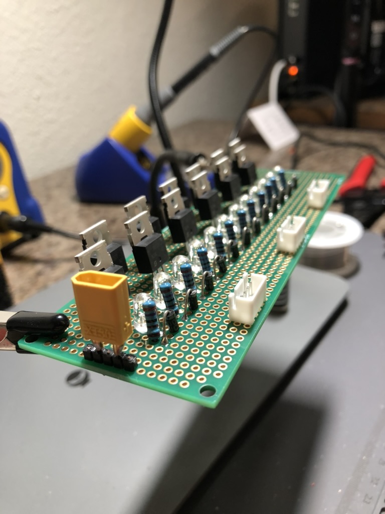
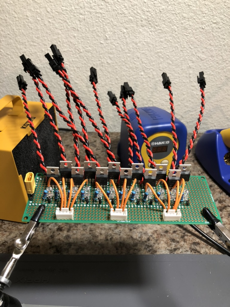
I started to look into it more because I was not just about to add components, possibly complicating the design, unless I understood the root cause. It was true that those LEDs should not be on unless there was some current running through the N channel MOSFET from drain to source. What if they were dimly lit, but the solenoid valve or igniter remained off? It turns out this is a thing and it is called leakage current.
Initially, I had a few false starts. For instance I would become confused after reading about some quantum mechanical tunneling that occurs in MOSFETs. “Really?” I thought. That sounded wrong. I was right to be suspicious but that is how I learned between the difference of “short channel” MOSFETs and “power” MOSFETs. The ones we were dealing with were definitely not short channel MOSFETs. After a week I was beginning to have an idea of what was going on. Heat was a factor for sure, but there was more to it than that. The behavior was also being exacerbated by ringing, and the fact the the gate threshold for these MOSFETs was low enough to be considered a “logic level MOSFET”.
I learned that together all three of these things contribute to the behavior that we had observed with ALARAs and more recently the ARALA v2. The leakage current of the MOSFET becomes more pronounced over time with degradation of the oxide layer within the MOSFET.
I started to think back to when we first started having problems with the engine node. After all – it had worked before. I remembered that there were lots of people coming in at different times and doing software tests. One morning, before our April static fire attempt, we came into the lab and somebody had accidentally left the stand powered on with the lid over the avionics box. It had been like this for hours. When we removed the lid for software testing that morning the ALARAs were cooking. It was very warm inside the box.
One thing that still didn’t make sense to me though was how come the MOSFETs on the ALARAs were able to live like two years whereas mine barely survived two weeks? I learned that each MOSFET has some leakage current. The leakage current for the ones that I had selected was significantly higher than that of the surface mount MOSFETs on ALARA. That was interesting. What was more interesting is that after comparing this value with others a trend was beginning to emerge. I looked up if the packaging for the MOSFET affected the leakage current and this turned out to be true.
That was how I decided that this new design would need to have different MOSFETs, ones with a higher gate threshold voltage, and also would need to be driven by a MOSFET gate driver to eliminate that ringing that was slowly degrading the oxide layer. Additionally, there needed to be some cooling incorporated, ideally not in the form of a box fan (if you read the last article).
(In case you were wondering the difference in the gate to source leakage current I_GSS between the ARALA and ALARA MOSFETs – it is +/- 10 micro amps for the RFP30N06LE – TO-220AB package and +/- 100 nA (or 0.1 uA) for the SIZ340DT-T1-GE3 – PowerPAIR 3×3 package.)
*****
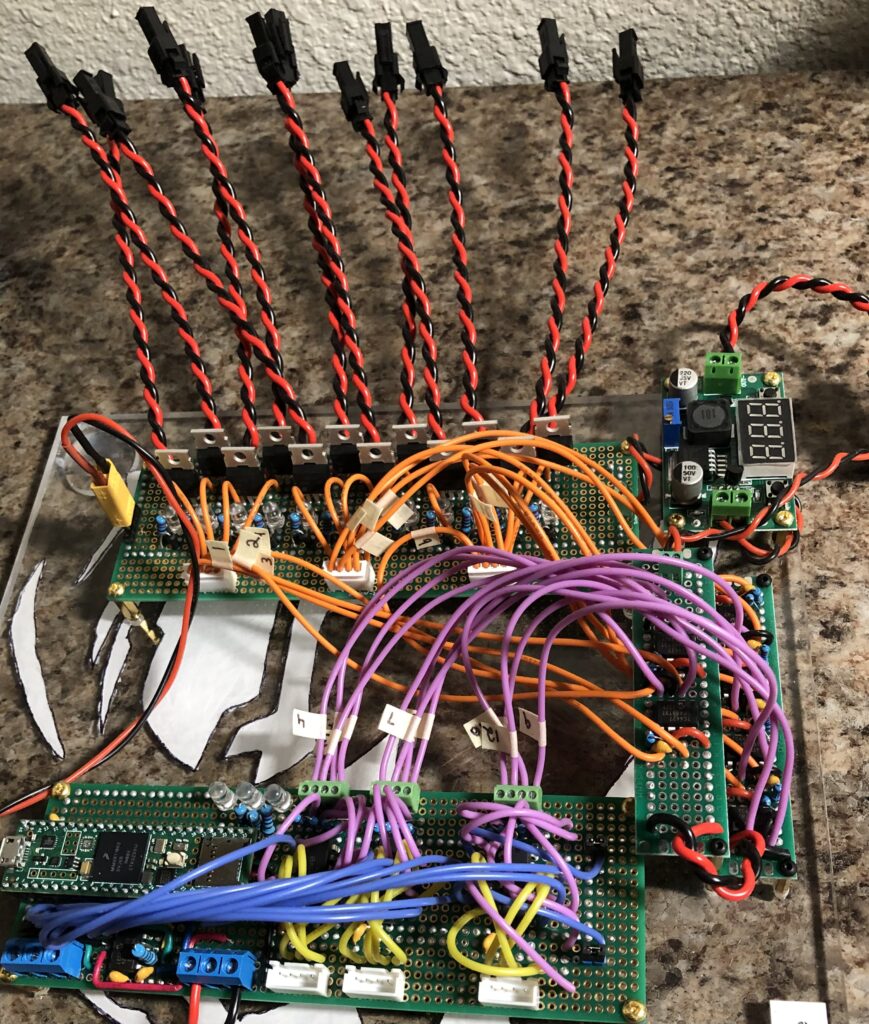
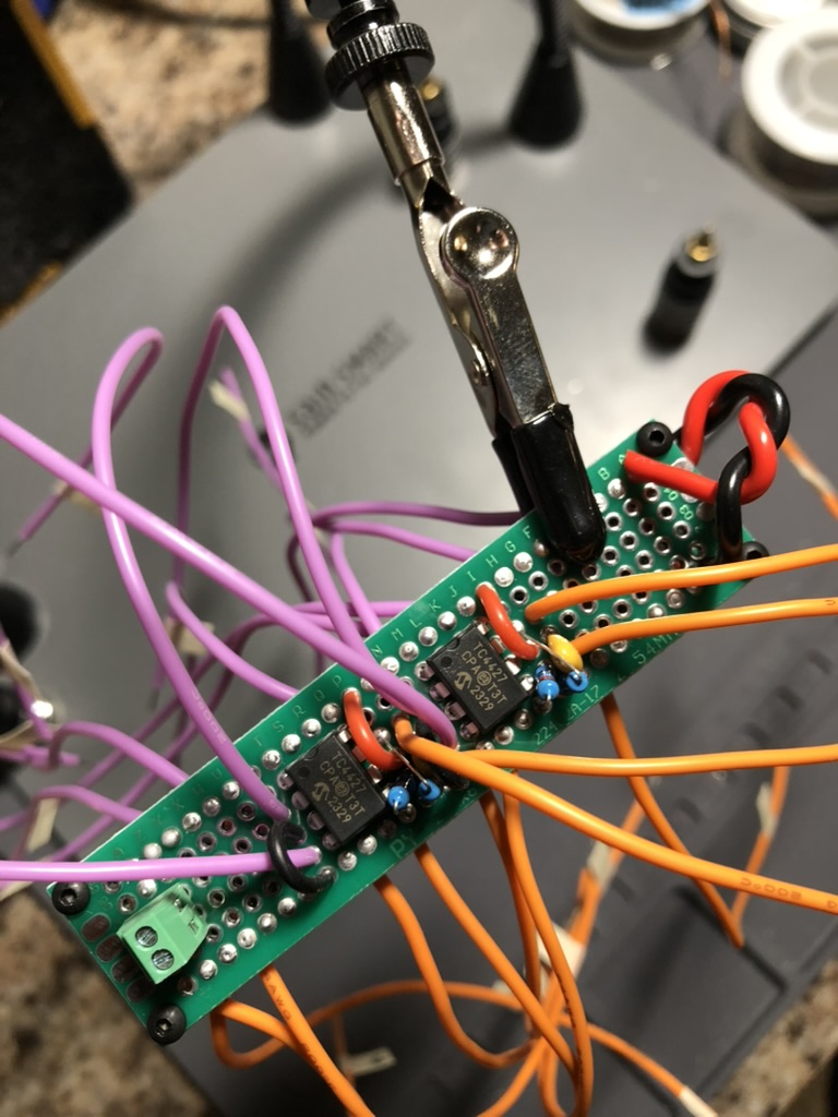
Chief has many similarities to ARALA v2, however, the differences were significant enough to warrant a completely new name – one less confusing than ARALA v2. The OR gates were still there. The inputs for switch box had changed from screw terminals to JST XH (something that you would not think would cause any issues, but surprisingly warrants a different pull-down resistor). These same JST XH connectors are used to connect the output from the MOSFET gate driver ICs to the perfboard that has all the MOSFET circuitry on it.
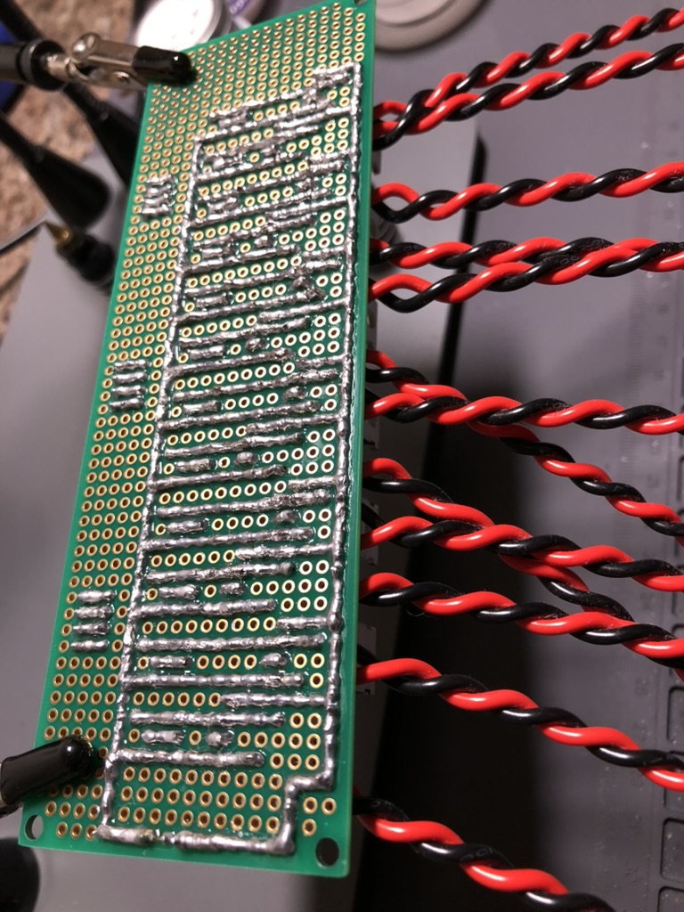
Another mistake that I had made on ARALA v2 was the addition of a decoupling capacitor. After spending some time on EE Stack Exchange I found somebody asking approximately the same thing, and the answer was no, don’t do that – you could damage the MOSFET. Those were all removed for Chief. The only other difference is that while the output wires are still connected directly to the perfboard, these are connected to female JST SM connectors, whereas on ARALA v2 they would have connected directly to sockets for the circular AMP bulkhead connectors on the EGSE. I now had experience with having to remove sockets, and reinstall the relay banks, and decided that there needed to be a faster way to do that.
I remember looking to see if I needed to include a pull-down resistor after the output pin for the gate driver, however I was not able to find a clear answer. Out of an abundance of caution I chose to include one. However I made a mistake and neglected to put one after the JST XH header on the actual MOSFET section, and because of this, once the system was powered on, all of the MOSFETs would slowly turn on. Another issue that I discovered was that if the input for MOSFET gate drivers was disconnected then that would also make them turn on. These were both huge problems – you can’t safely use a design like that for flying a rocket – let alone even using it for testing. I decided that this current lay out would serve as a learning tool. If you were to reproduce the design on a PCB, then you would not need those connectors and the problem would go away.
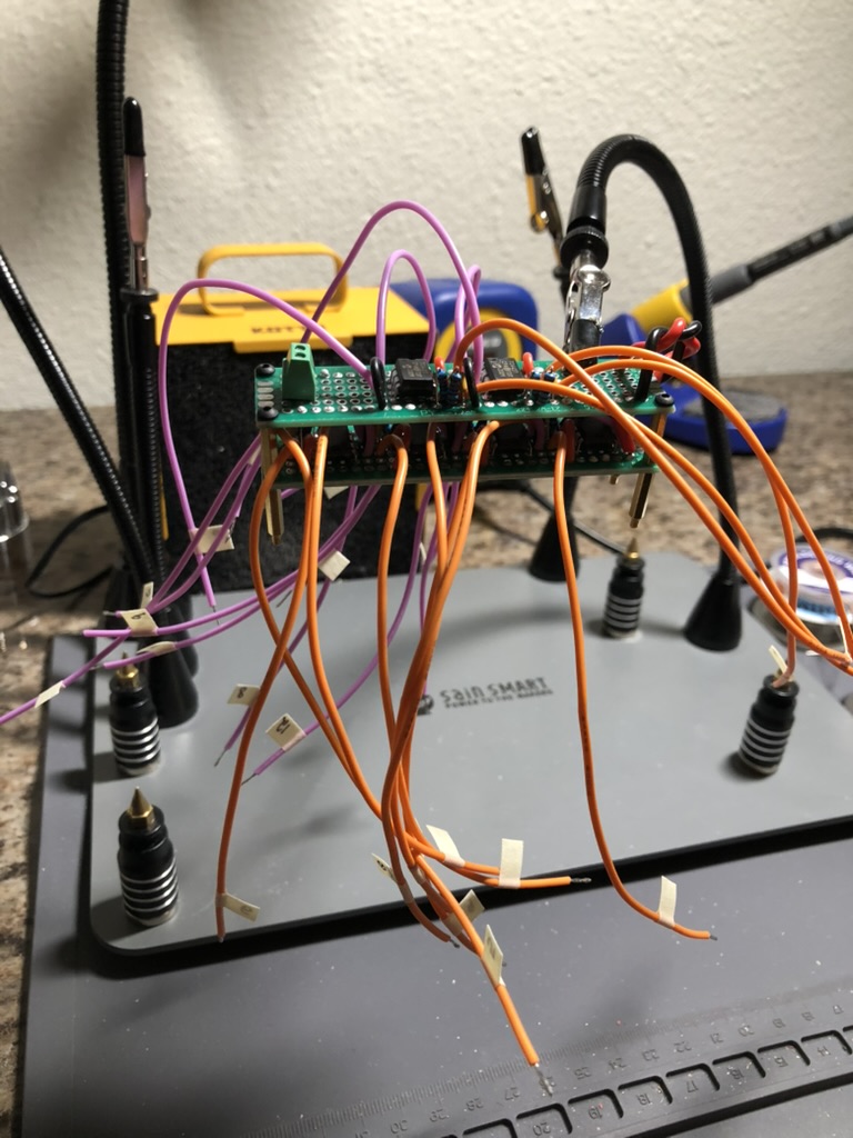
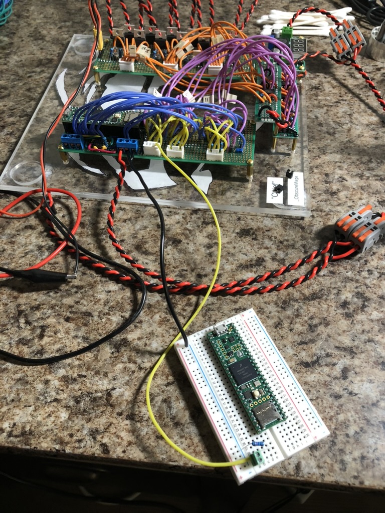
Probably the most interesting development with Chief was the pull-down resistors for the input from the switch box. I had written a small test program that would cycle through each of the Teensy 4.1 pins connected to an OR gate input. What was strange was that the program only worked a little. There was a definite trend, you could tell that the program was running, however there were HPO channels that were on when they definitely should have been off. The program was written in a way where there would only ever be one on at a time.
I was running out of ideas. I could not understand why they would be on like that. For whatever reason I decided to grab the stranded wires, with a silicon sheathing, that extended from the output of the gate driver ICs to the input connector on the MOSFET board. I was really surprised when I found that by squeezing the wires together I was able to get MOSFETs to be on that should have been off. (Truthfully, I did not take very good notes during this time period, and I may have been squeezing the inputs for the OR gates coming from the Teensy together.) This was very strange. I did some Googling and found out that what I was observing was called inductive coupling. Suddenly that problem that I had faced with the switch box began to make sense! How to fix it though?
The first thing I did was I decided to add a pull-down resistor between the output pin on the OR gate and the screw terminal for the input to the MOSFET gate driver. That did not fix anything. Next, I thought maybe if I ground the input for the the switch box inputs to the OR gate – maybe that would help. I got out a mini breadboard and connected a common ground from Chief to the breadboard using a clip on Y junction. That actually had some success – the program was now running correctly. That meant that something was wrong with the pull-down resistor though. I was using a pull-down with a value of 10k ohms. I had learned through conversations with electrical engineering masters students, and stack exchange, that this was a good value to start at. However right now it was failing. The next thing I did was instead of connecting the switch box input value directly to ground – I put a resistor in series with it and turned the system on. If I remember correctly, going through my small binder of common resistor values beginning at 10k ohms, the problem went away with a pull-down resistor value of 2.7k ohms. So I think I went down a little bit more, to provide head room for whatever this was, and went with a resistor value of 1k ohms.
I also made a change for the latch circuitry where the current would first pass through a diode, leading to the the input pin on the OR gate, and then on to the input pin with a second wire connecting to the latch. I replaced all 10k ohm pull-down resistors within the latch circuit with 1k ohm resistors as well.
Chief is still being developed. The plan is to submit this as part of a product idea for the Sunstone Innovation Challenge at school. The design definitely needs to be refined before it is committed to a PCB, but I believe that there is a lot of value in this. I think of everything that I have learned just by having the opportunity to program the ALARA that BLT used, and I consider myself very luck to have had that opportunity. I know for sure that I am a stronger programmer, and a stronger student in general because of that experience. If I had to identify the largest source of growth I’ve had within my time in school, then I would point to ALARA and the role that it had within BLT. Unfortunately, like I mentioned in the CAN article, it was retired before the ’24-’25 school year and for a good reason. However, if people have an opportunity to program a board that can fly an amateur liquid propellant rocket, without all of the headaches ordinarily associated with student made PCBs, and without the price tag of professional flight computers, then I think that can be a source of a lot of good.
I think of all of the times my peers and myself got hung up on some weird behavior, “weird behavior” at least for a computer science major, and it ended up being a bit that was incorrect within a CAN frame, or leakage current, or inductive coupling, but you have no idea that is the case at the time. You then must spend time rooting out evil within the avionics system, and it takes away from time that could actually be spent doing rocketry.
Resources:
1.) Avionics meeting slides following the water flow test on campus:
Back to top