ESRA – EGSE
Code:
No code for this project.
Date:
December ’24 – April ‘25
Why:
I was asked to create an electrical system for ESRA at CSULB.
What:
Around December I met with a senior member of ESRA who had since graduated and they mentioned that they were interested in creating an electrical system for their ESRA team. They needed to convert a rocket that had flown once before on a solid propellant motor to one that could have a sled inserted into it and flown on liquid propellant. They didn’t have anyone in mind to do the electrical work and asked me if I wanted to do it. It sounded like an interesting project. The electrical system that they wanted would have been a network larger than any other that I had worked on so far.
I can remember having some reservations about some of the system requirements. For example they wanted to use RS-232 implemented with UART or alternatively just straight up UART. I was heavily biased toward CAN at this point and thought that it was a better communication protocol. I was looking back at my notes before this article and I had put together side by side comparisons of RS-232, RS-485, and CAN. Within the OSI model (Open Systems Interconnection) the CAN protocol is defined by both a physical and data link level. In this way it is comparable to UART which also uses both. RS-232 and RS-485 are not communication protocols alone, but a physical standard onto which they can be built.
I wanted to compare them all to learn more about the pros and cons and also to refresh my memory on CAN, and also just to try and have an open mind about what other methods of communication were available for the network in question. I sent videos on CANs fault detection and how the protocol has the ability to silence a node if it is messing up by using things like error states and error counters. I really like that CAN’s IDs have priority. I believe that is a very powerful feature, and I leveraged that heavily while developing the CAN software for BLT. Open commands for valves were always greater than close commands.
Often times these discussions were met with questions like, “Do we really need that?” The concern at the time was that CAN was overkill for what we were trying to do and that the goal for the club was to understand every detail of what was occurring under the hood (at a software and hardware level). This extended to the microcontroller that the group wanted to use which was an STM32. It was chosen because of all the settings within the IDE for understanding embedded systems programming. By comparison much of what I had done in the past was using PlatformIO within VS Code for Teensy’s and ALARA (which was a larger fancier Teensy). I had used CubeIDE before for working on John Garvey’s K-101 rocket, but that was about it.
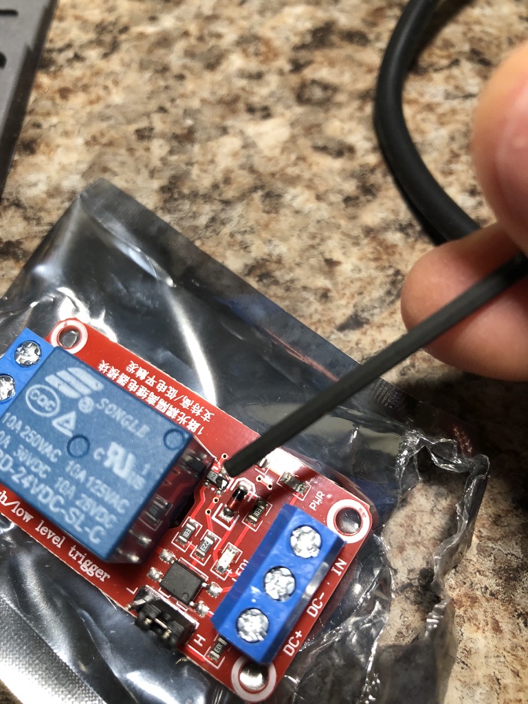
There was another requirement that I thought was unusual and that was using relays instead of MOSFETs. Many of the members within ESRA were once members of BLT and they also had experienced the ALARA’s HPO channels malfunctioning. I tried to explain that I was confident that I could prevent that from happening if ESRA chose to use MOSFETs, but they did not spring for that. I could see that if I wanted to work on this project I would need to use tools that would not be my first choice. I tried to focus on the positive aspects: it was a good opportunity, the relays may not be as fast at switching but they were robust and sufficient for what we were trying to do, and lastly it looked like there was a lot that could be done with both UART and the STM32s in terms of creativity so I was looking forward to learning more about both.
*****
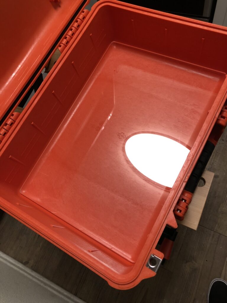
Eventually we returned from winter break and around week two I was invited to a meeting. After that I got right to work. So far the group had a switch box that was based off of my design for BLT. This meant that it was going to have many of the same problems that my box had as far as keeping the signal voltage on the appropriate conductors. Initially, we were going to redo the wiring because they currently all shared the same ground wire. However, the box was also 3d printed and there were holes for the switches that needed to be reprinted as circles (they were presently cut by hand as rectangles and had no way of being retained). Instead I suggested using a metal tool box – like I had seen in Garv’s garage and then just placing a piece of acrylic over the top, where a tool holder would go, for the switches. I had recently watched a video of BLTs static fire attempt, and they had the switch box that I made turned sideways. Evidently the box was too large for the narrow tables within the LCC (Launch Control Center) and had to be oriented differently. That was not what I had in mind when I created it. I suggested instead that we put the bulkhead connector on the side of the tool box so that we did not run into a similar issue, and that is what ended up happening.
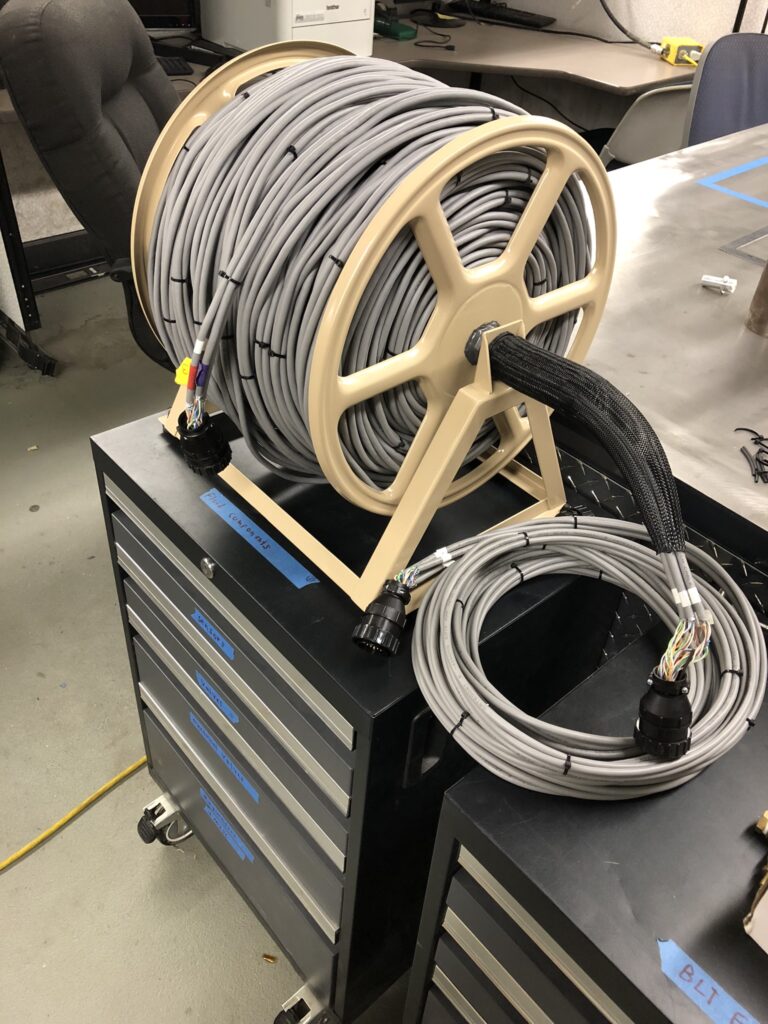
The group did not have a cable and we would either need to create one or purchase one. For the amount of conductors and the length that this cable would be – buying one was completely off the table. Even building one was going to be expensive. I had purchased this garden hose reel with the intention of converting it into a cable spool holder. The idea was at in the lab you could have it on wheels, like a dolly, then when you went out to FAR you could slip on these skis and it would be like a sled that you could pull around. Additionally, the cable that I had in mind was going to weigh 60 pounds so asking a student to haul that around seemed unreasonable. Nobody would want to do that, and I knew that since I was helping out with the electrical system that this responsibility would more than likely become mine. It was an effort to be kind to my future self.
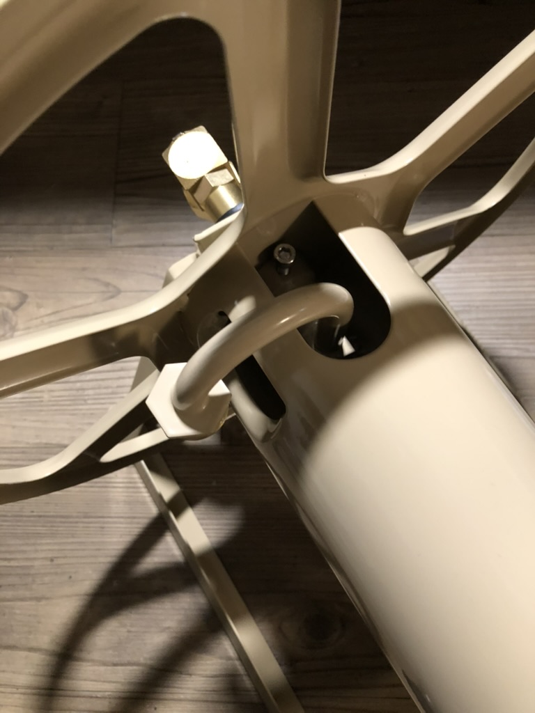
Repurposing the garden hose spool was a lot of work but it ended up turning out really cool. My favorite thing about this was that the spool ended up accommodating all of the cable length perfectly. What needed to be done was first there were sections of the plumbing on the spool that were clearly meant for a hose (duh), and we would not be able to put four CAT8 cables through that small of a tube. I removed all those one evening at home, but there was another problem. I was going to have to buy a straight pipe to replace the strange J and L shaped ones that I had removed. Without this – the spool would only have been supported on the side with the handle. We needed a way to connect it to the frame of the hose holder. I found one on Amazon that would do the job: “Beduan Stainless Steel Pipe Fittings 1/2” NPT x 1/2” NPT Male Threaded, 4” Length”.
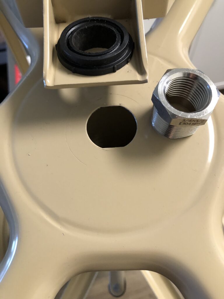
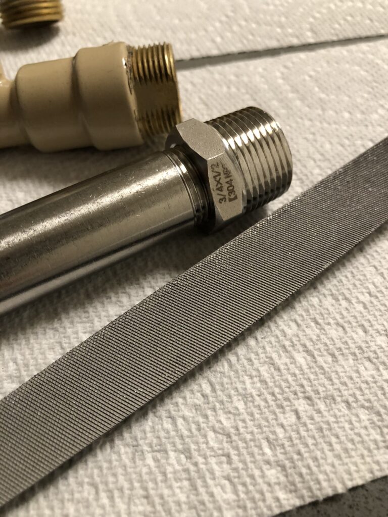
I realized that this pipe was just a little to thick to fit through the plastic collars on the frame – so I filed the interior of the collar down until the pipe went through. Next, there was another problem. The hole on the spool that this pipe needed to go through was not perfectly circular. There were two flat edges parallel to each other and the rest of it was round. (My guess is that they do things like this to prevent people from making modifications to their projects.) Not only was the hole not circular but the hole in the spool was also larger than the pipe and would require a reducer (“Beduan Stainless Steel Reducer Hex Bushing, 3/4” Male NPT to 1/2” Female NPT). I had to either file the spool itself or file down the threads on this new reducer. I decided that filing the threads would probably be best. (If I made a mistake on the reducer it would be less costly than purchasing a whole new garden hose holder and repeating all the work that had been done so far.) I did this using digital calipers to record the dimensions of the original fitting that I had removed. I wanted to get this new one as close as possible to the old one.
Once that was finished my hope was that I could just use the old nut that was used to secure the old pipe on the other side of this reducer on the interior of spool. However, when you spun the spool with the handle it would start to rock up and down. The pipe remained level most of the time, but the nut was not fitting tightly enough on the reducer. I was unable to get it to fit securely over the work that I had done filing the threads down. Right now it was only a little annoying because of how noisy it was, but I was not about to find out what would happen once we put 60 additional pounds on it.
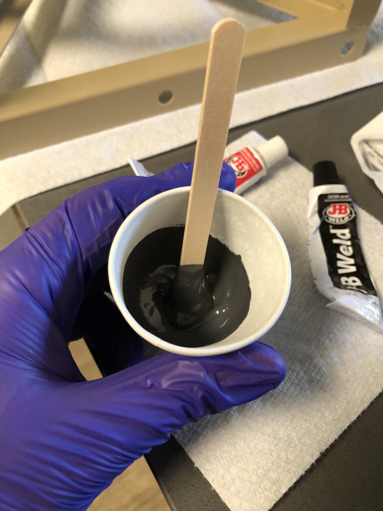
I decided to orient the spool vertically in a position where I knew the pipe was straight, and I applied JB Weld over the reducer and where it fit into the spool. After a day, I checked on the rotation of the spool and it was perfect. I am really surprised that everything worked out as well as it did. (There was one mishap with ordering the wrong sized fitting initially, but I was able to do a return and got the size right the second time … whoever decided that 3/4” NPT would actually not be 3/4”, but rather a measurement other than 3/4” laughed themself to sleep that night. I know they did.)
*****
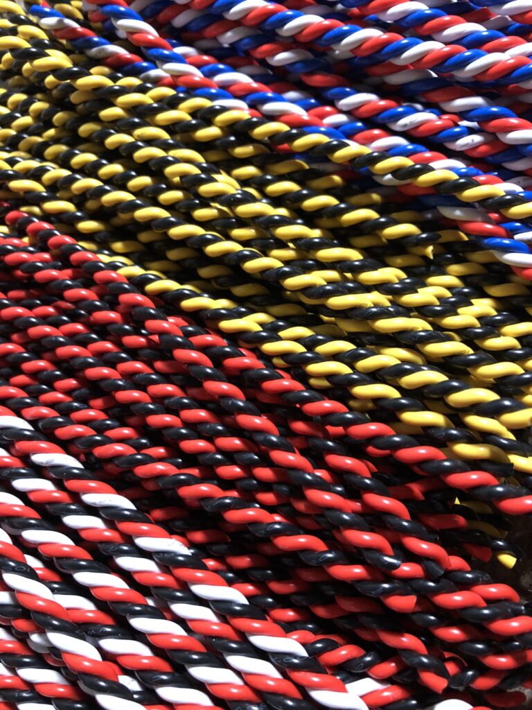
The next thing to do was to build the cable itself. I had done some research and decided that the most cost effective solution would be CAT8 cable. I liked the idea that each twisted pair had their own set of shielding, and then each set of four twisted pairs had additional shielding. After my experience with the cable made for BLT I was very much in favor of all the shielding I could get. The cable length needed to be the same as the one that was used for Garv’s K-101 launch (333 feet). The closest that I could find to that online was 400 feet and we would need four of them for 1600 feet of cable total.
I brought the cable, zip ties, and modified garden hose holder into the lab one day and Marvin (from the ARALA v2 article), Luke, and myself knocked it out in one night over the course of about 6 hours. We ended up needing to add a loom to the inside of the pipe so that it would not scuff the cable over time. To understand how this would all work you would attach the end of the cable to the EGSE container, and then you would run that cable back to the bunker. Next, you would attach a twenty foot extension from that part I just mentioned extending through the pipe and loom out of the side of the cable spool, and that part would connect to the switch box. The reason the extension was necessary is that otherwise you would have this long piece of cable flopping around on the side of the spool which would have been less than ideal.
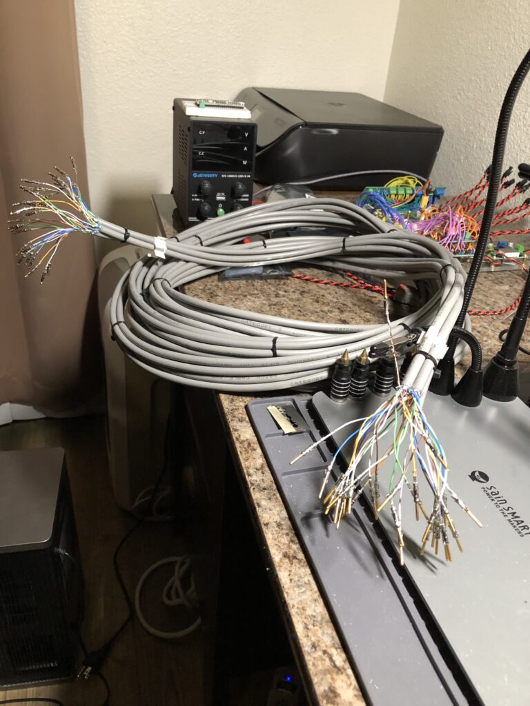
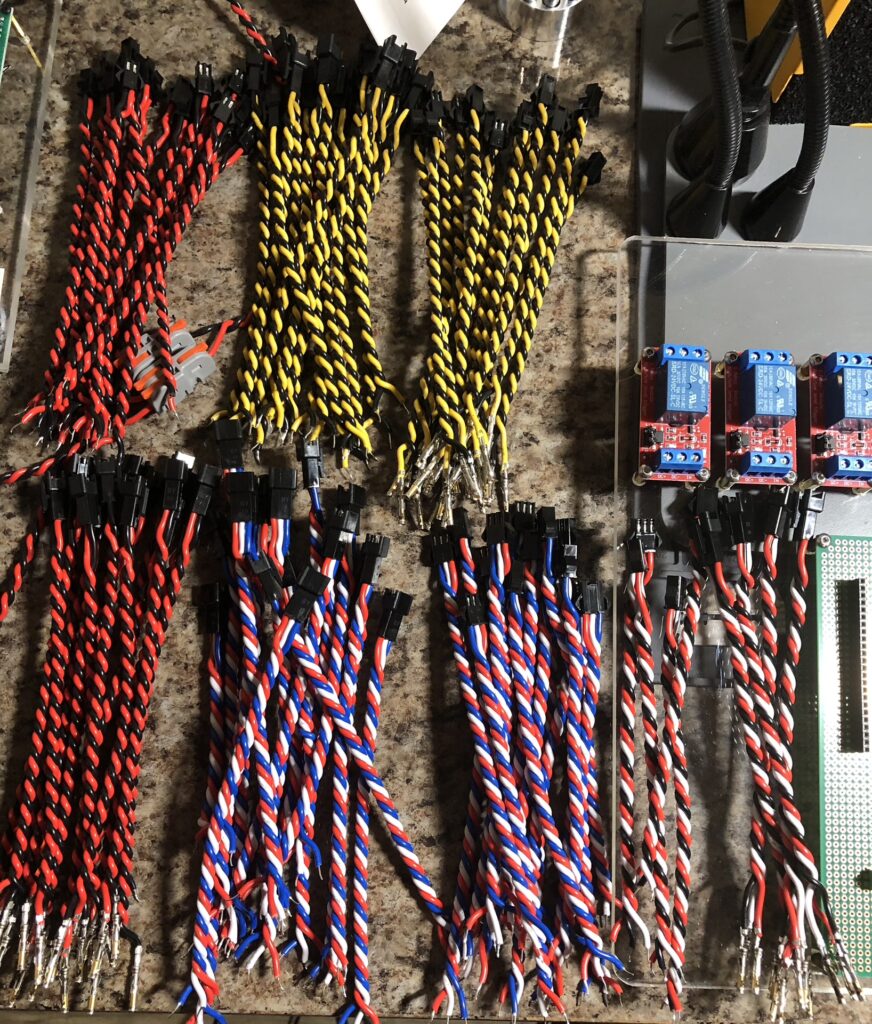
The only thing remaining to do was to do all the crimping for the cable. There was a total of 128 size 16 contacts that needed to be added for the AMP circular connectors. 64 for the cable itself (32 for both ends), and then 64 for the 20 foot extension. Even though these were size 16 contacts they were made for 26 AWG wire. I did not think that this would be much of a problem after all I had done plenty of JST SM harnessing in the past. However, this harnessing proved to be a learning experience. I think out of the first 10 I tried I broke like 6 or 7 of them, but after that I started to figure it out and it was no problem. Before doing the harnessing I ended up applying solder to all of the wires that I had stripped so that they would all stick together during harnessing. (Normally I wouldn’t have done this however this individual wires were so small that they could be difficult to see.)
The harnessing went mostly smoothly except for one mistake. I purchased a female inline connector for the extension to connect to the cable, but on the cable I did not have the correct mating product. I had the male connector that you would use for a bulkhead connector as this was all that I had needed them for in the past, however in order to make this work I would need to attach an inline male connector to match the female one on the extension cable. I started to remove the contacts, using the appropriate removal tool, but even then I had trouble removing them. I ended up breaking quite a few contacts and I decided that it would be faster just to cut the connector off and re-harness the whole thing. I decided to connect the exterior shielding for all the cables and place them in one contact in the last (37th) position of the connector. I decided that this could be grounded later on, on the EGSE side, to help reduce any noise. Once that was finished the cable was done!
*****
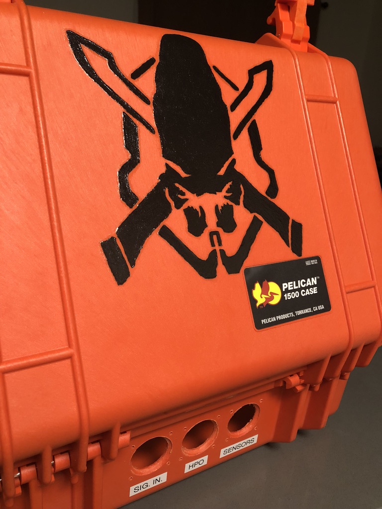
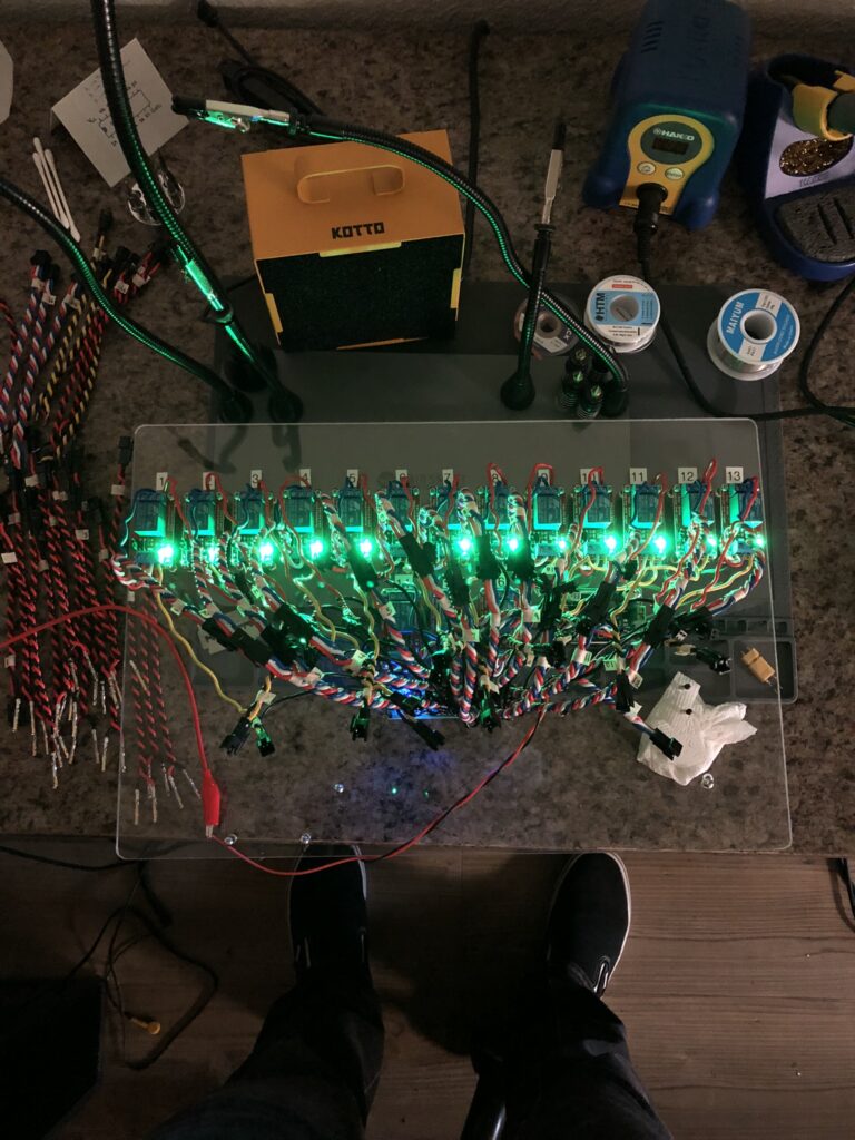
The next thing to work on was the EGSE container. I was really excited about this because I had a lot of ideas on how to make improvements after my experience with the EGSE for BLT. This one would be smaller and more simple. Instead of using a relay bank as I had done in the past we would use individual relays to isolate the signal and return path for each switch and each high power object. I had read where you can reduce inductive coupling by using solid core wire, and I also read that dedicated ground paths were important. Keeping the return path close to the signal, minimizing the distance between the two, was also important. If you look at the inside of this box you can see that everything is solid core and all the pairs have been twisted. Even on the perfboard traces there were steps taken to ensure that the ground and signal paths are far away from each other even if they connected to a common ground rail or common power rail(24V).
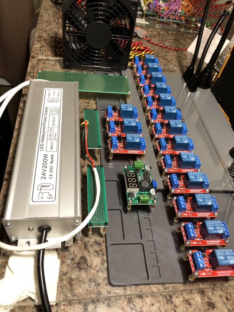
There would be a total of 16 relays: 12 for valves with one extra, and two for igniters with one extra. We would be using all of the conductors within the CAT8 cable. I decided to do something different for the relays responsible for igniters though. Taking lessons from BLT’s experience at their most recent static fire, and what I had seen Garv do before, I decided to make a separate perfboard for the igniter relays. This one would be powered by three 9V batteries in series that somebody in the bunker could connect and disconnect. This would be unique in that if somebody attempted to actuate an igniter before we were ready, then it would not be a problem because nothing would happen since the relay was not even on in the first place. There was a separate 4 cavity bulkhead connector attached to the EGSE for this new igniter cable.
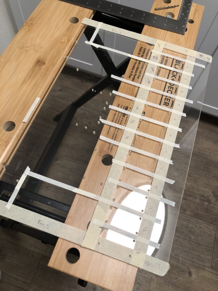
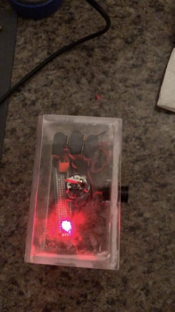
On the console side the igniter cable would connect to this little acrylic shunt box that had a key hole that I had inserted into it. On Amazon, I found this little metal cylinder that was a switch, and you could open and close the switch by using the keys that came with it. It was pretty cool twisting the key and watching the red LED come on within igniter shunt box. That box was connected to a larger piece of acrylic that had the legs of a stand for a 10” Raspberry Pi Display. There was also room for a 4” fan on the far left side that was secured by velcro ribbon strips and could be removed. The idea was that in the future this would be how wireless communication would be made possible. On the EGSE side there was of course room for a microcontroller as well as a buck converter and two brushless DC fans for cooling.
There were three main 37 cavity bulkhead connectors on the EGSE container: one for signal in, one for high power out, and a final one for sensors. There were two 4 cavity bulkhead connectors: one for data or alternatively an antenna, and then the other as I already mentioned was for the igniter cable. There were also many holes drilled in a circular pattern so that the fans could pull air in and push air out. This of course meant that we would need to install a filter so that the electronics would not become covered in dust.
Unfortunately, as the semester went on I realized that I would either need to withdraw from a class, something I had done before as avionics lead of BLT, or let the group know that I would not be able to continue the work. I made the difficult decision to focus on my classes for the remainder of the semester. I was confident that enough work had been done that ESRA would be successful with the goals that they had set for the group. In terms of harnessing the only thing remaining was connecting the sensors and high power objects to the EGSE container. The only other thing would be getting sensor readings to the pad, and as we had learned from working with Garv, this could be done even using gauges and an old iPhone. It did not need to be fancy.
I am lucky to have had people reach out to me to help create an electrical system for the launch vehicle. While I did not get far enough along to create the network that attracted me to the project in the first place, the electrical system remains one of a kind due to the unique system requirements that I was given.
This was a valuable experience for me because it made me realize how nice a wireless solution would be. Wireless communication is something that Garv had expressed interest in, and something that we were working toward during the K-101 project. Half Cat Rocketry also uses wireless communication within their Mojave Sphinx design, and that design is regarded as a good entry level project for liquid propellant rocketry. This was also an opportunity to work with another team, on another electrical system for another launch vehicle which was also exciting.
It was also valuable because there were things that seemed like a great idea on paper that ended up proving difficult to do in ways that I was not anticipating. For example using JST SM connectors for each relay required crimping 160 (16 relays times 5 screw terminals on the relay times 2 male and female) small contacts. This was done to allow for speed later on, but I realized having the igniter relays below the valve relays was a mistake. It made them inaccessible. If you needed to replace an igniter relay there would have been so many conductors in the way that you would have needed to have disconnected all the wiring responsible for valves first before replacing the igniter relay in question. Later on some members suggested having a custom connector made where you could plug a whole bunch of things in and out all at once, but this does not really solve the problem: you would still be removing contacts from a larger connector if you needed to replace a relay.
I still think the two and three contact JST SM connectors were a good call because even though they were a little annoying to deal with for this layout, I would argue that it would have been much more annoying to screw and unscrew the screw terminals. For example, when I was putting the EGSE container together, I made the mistake of accidentally connecting common ground to common power on one the relays, and when I powered the system on I heard a POP! I noticed a bad smell and then that one of the relays was off. At first I thought that maybe the relay was bad. After all, when we were creating the first ARALA I can remember that one of the relays on one of the banks did not work at all. That was not the case here though. I realized my mistake while I was removing the wires from the screw terminals of the relay. I also saw where a transistor had exploded on the relay. Whoops.
If I were to do this project again I would still use the JST SM connectors. I still think it’s a good idea: if one of them ever were to stop working, then you could go out to the pad and quickly swap out that high power output channel with the spare relay. The idea is that you never make an involved replacement in the field. One thing I would do differently though is I would have used a larger container, larger perfboard, and used more space to make all the connections with the relay. I would also avoid soldering the solid core wire directly into the perfboard. In the future I would use screw terminals to make all of these connections. As far as harnessing goes there were also 32 sockets for signal in and 32 for high power out, but those were easy because they are much more forgiving to work with (they were all size 16 contacts for 22 gauge wire).
Resources:
1.) ESRA Notes:
Back to top