Beach Launch Team – ARALAv2
Code:
Date:
August ’24 – September ‘24
Why:
Now that the club had the ability to fire an engine with the EGSE we needed a solution for actually flying the vehicle.
What:
Sometime in July, while working in John Garvey’s garage, I had a conversation with somebody who had been in BLT for some time. They were asking about the avionics that I had planned for the club next year. Specifically we were talking about the pneumatics section of Garv’s K101 rocket. When the rocket left the pad, both of the main valves would be held open because of how the plumbing was set up on the vehicle. However, this was not the case for the Theseus rocket that BLT was building. At the time, the main valves were actuated by a five-way solenoid valve and a Kinetrol. If you tried to launch this rocket the same way that you launched Garv’s it would have gotten a few feet off the ground, and would have started falling after the quick disconnect was removed, and the main valves closed. The only power on Garv’s rocket was a 2 cell LiPo connected to the Quantum Eggtimer I had assembled.
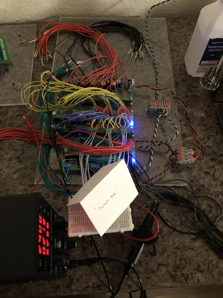
“So, how do you launch using the switch box?” They asked. “… I kind of figured they would only use that for testing, and then use the CAN bus for the real deal.” Wrong answer. They told me “No. You need to figure that out.”
*****
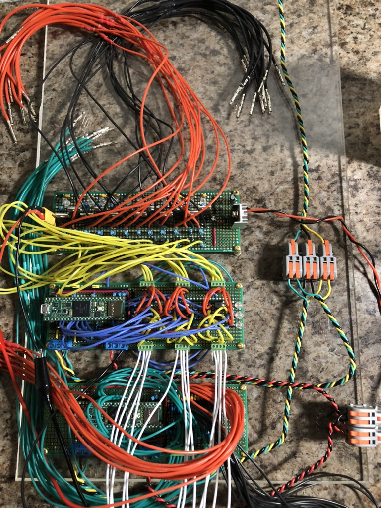
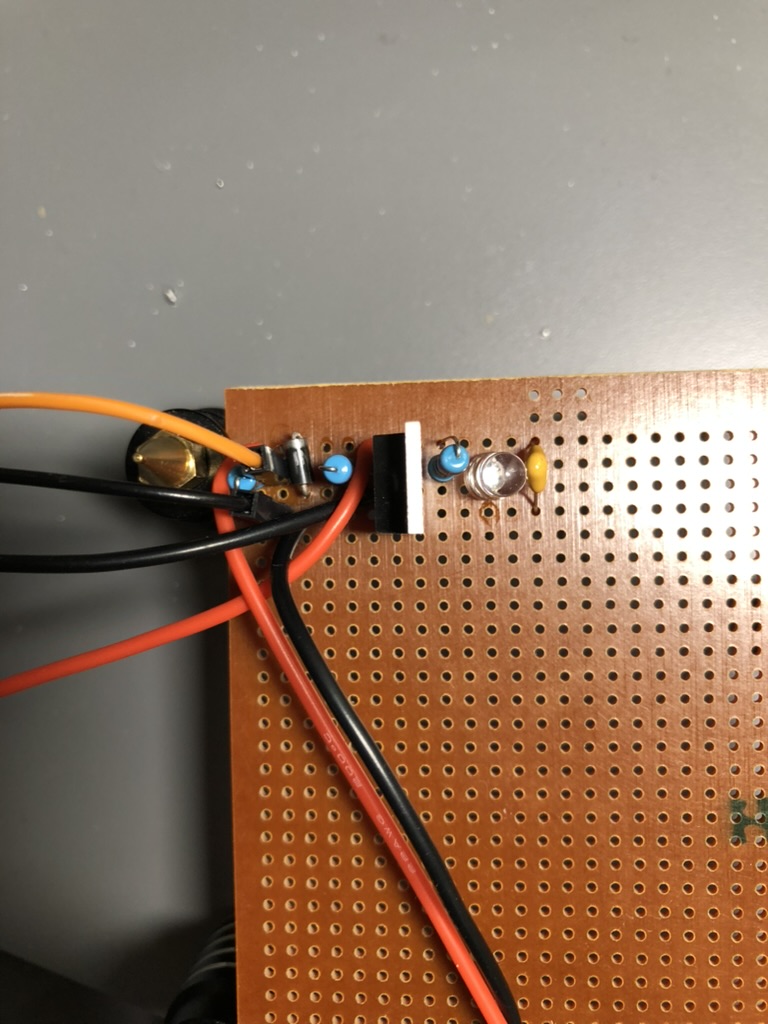
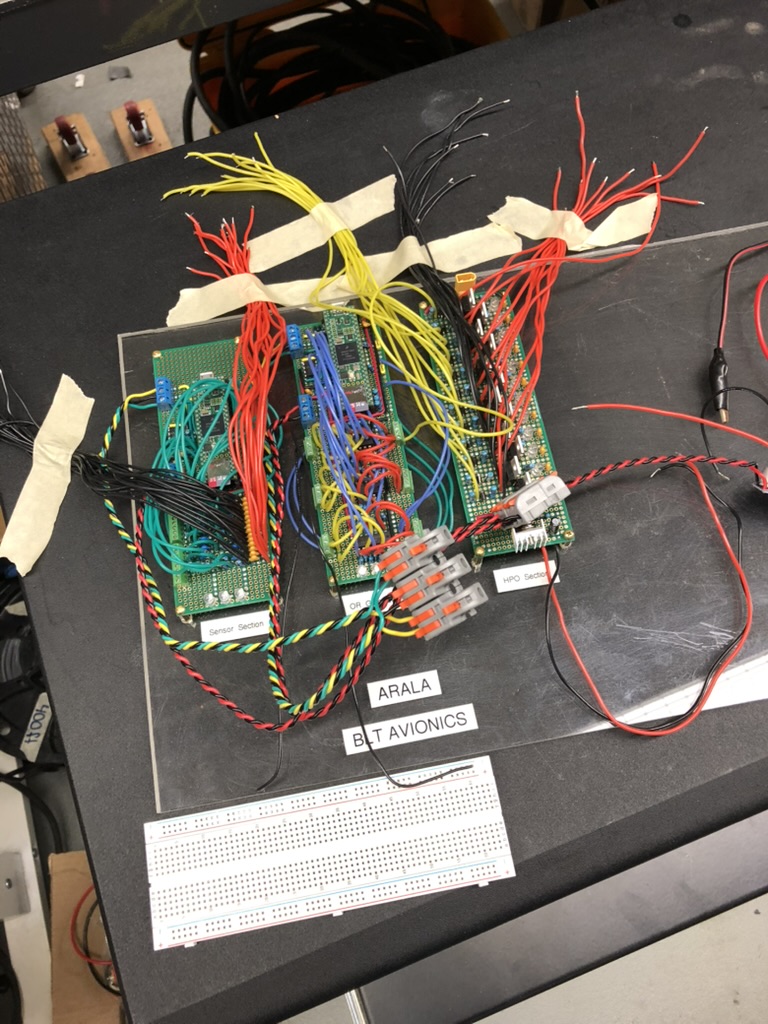
Some time passed and I started thinking more about it. There needed to be a way to preserve a signal sent from the switch box, and there also needed to be a way to have the system accommodate a signal from the switch box OR from the CAN bus that would connect the GUI to the rocket. I did some research to find out how did other people do this? I had talked to Garv one morning about how he had achieved multiple inputs, and he said the way this was done was to create either a Y-junction or an OR gate. That part was done: we could use the signal from the switch box and the signal from the GPIO pins from the Teensy 4.1. I was excited by this because the output voltage would be high enough to use the MOSFETs that we were originally trying to use (RFP30N06LE). This meant that we would not need to use the relay banks on the original ARALA, and that we could use the original circuitry that the previous avionics lead had created. That was nice because it was one less thing to worry about.
I figured out the second part by watching a Ben Eater video on SR Latches. The first part of the video he shows a more simple latch where the output is just fed back to one of the inputs on the OR Gate. I figured it did not need to be any more complicated than that. As long as the rocket got off the ground, and all the valves stayed open until the vehicle reached apogee, then I would call that a success.
*****
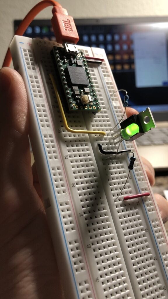
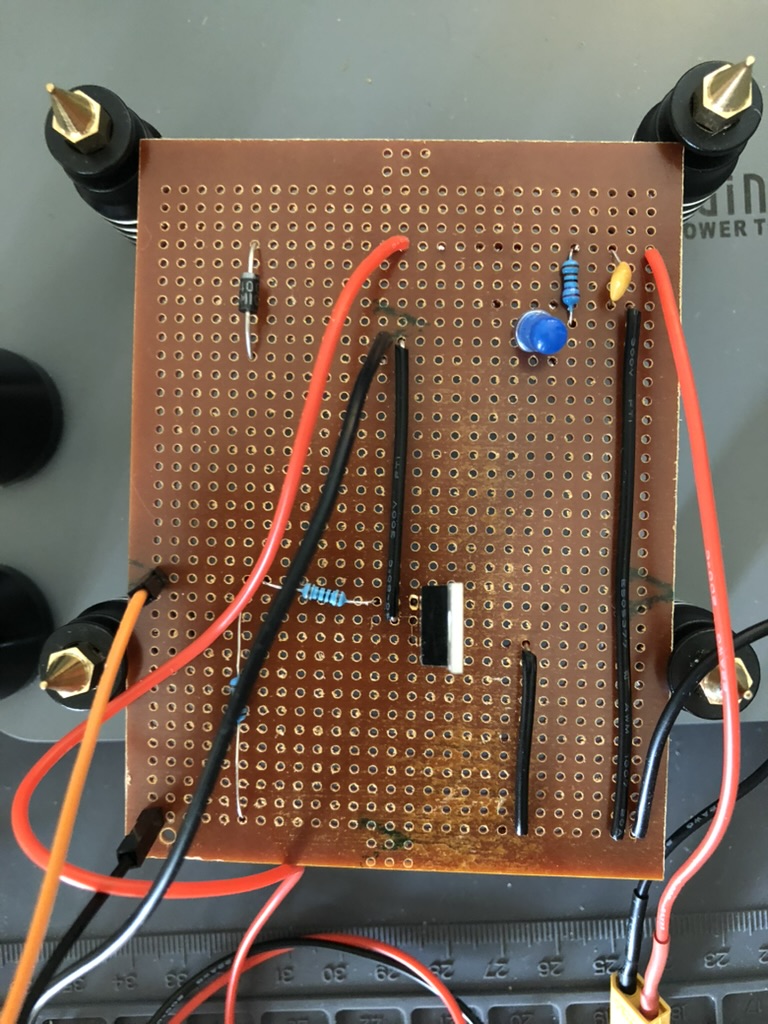
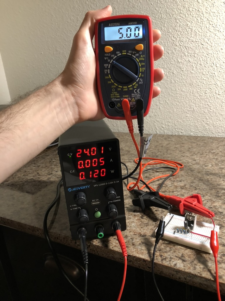
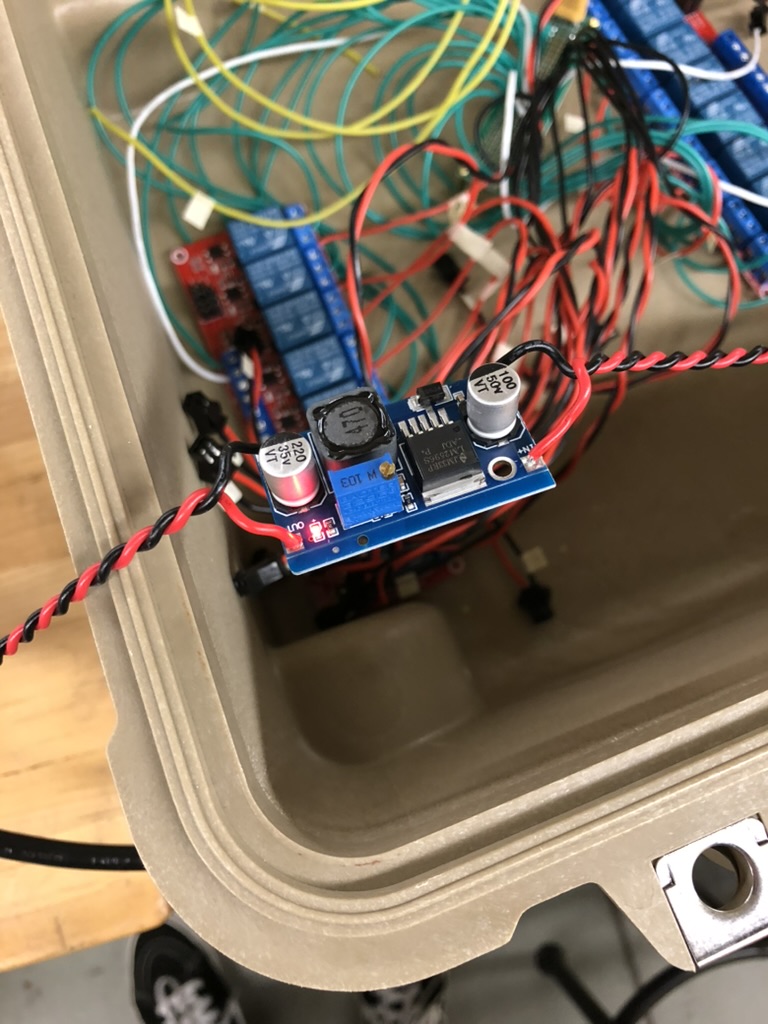
I made a whole bunch of mistakes on this design. The first mistake I made was I used a linear voltage regulator to go from 24V at the end of the MOSFET section to the 5V at the beginning of the sensor and control sections. On the original ARALA design we used a switching voltage regulator, a buck converter, to achieve this. At the time I can remember thinking that it was unnecessarily complicated, and if the same result could be achieved without having to use COTS (commercial off the shelf) boards, then we would be better off for it in the long run. This was how I learned that electronics do not like heat. This was also how I learned about a careful distinction made within the TR (Technology Readiness) levels that NASA uses. TRL-4 says, “Component and/or breadboard validation in laboratory environment,” and TRL-5 says, “Component and/or breadboard validation in relevant environment.” For me, the difference between the device sitting on my desk in my apartment, and it operating within the EGSE container, was the difference between it working fine, and it not working at all.
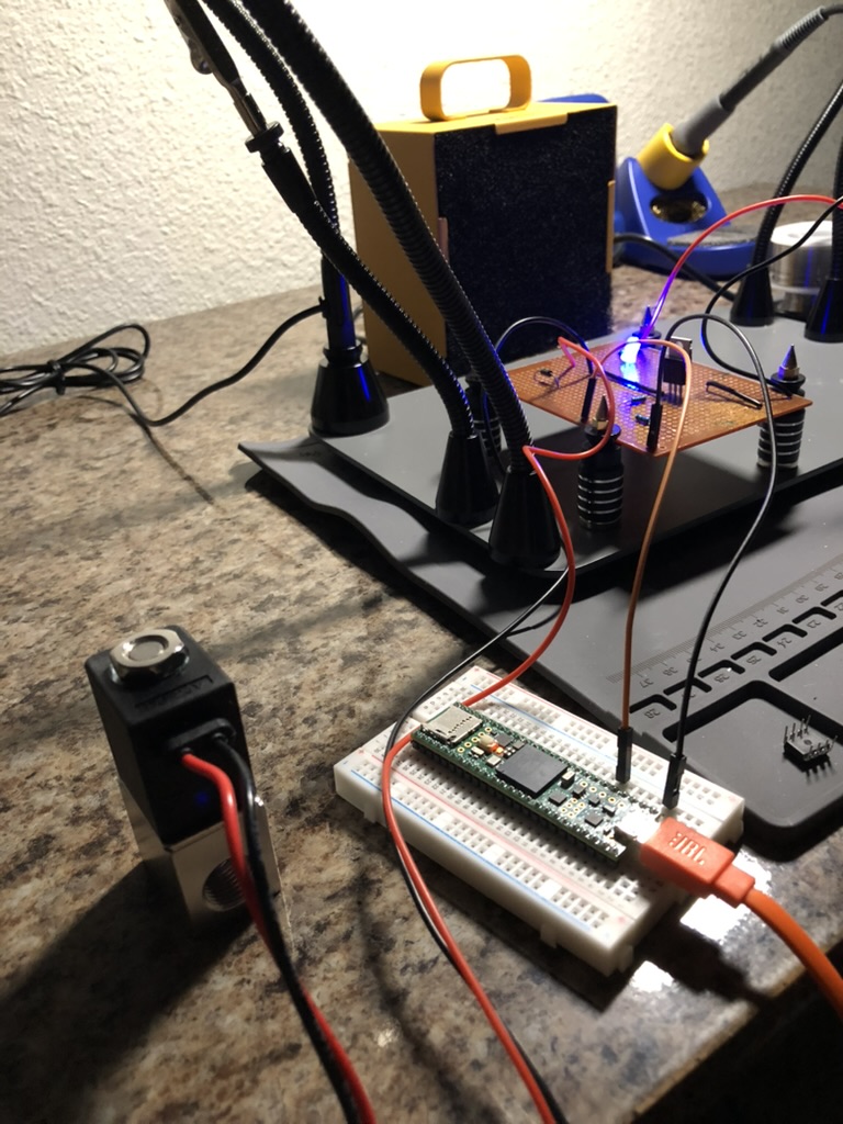
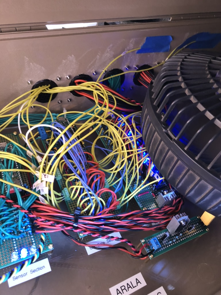
One night I was in the lab and was having some success with the ARALA v2. If I remember correctly, we were having some trouble with the new Raspberry Pi that we had installed earlier that day (the solution ended up being enabling an SPI setting that I did not know about within the settings). After that though it looked like the dry run scheduled for the following day would be a success after all. It was 9PM, and just about then a member from the SAE (Society of Automotive Engineers) was passing through, and I wanted to show them how the OR-gates on my design worked. As an electrical engineering major I figured he might be interested in it. Anyway, right then everything fails and the ARALA v2 starts turning off. You could tell by the LED lights for the vehicle’s state that the device was trying to remain on but was having some problems.
He said, “One minute I want to try something.” When he came back with a little four inch fan with a cover on it, like the type somebody would put on their desk, I thought to myself, “Oh no. This guy is about to waste my time!” You could not believe my shock moments later when everything started working. Marvin had saved the day!
The dry run the following day went good for the most part. We swapped out the small fan for a larger box fan and kept that on the box. There were a couple little weird things: for example the state for the vehicle would get messed up on the GUI and you would need to cycle it. What was happening was that only one of the Teensy 4.1s should have had the code to control the vehicles state, a responsibility that had previously been divided between the two ALARA pcbs. Both of the Teensys were connected to the CAN bus, and the idea was that one would be responsible for the state of the vehicle and the other would just be responsible for giving sensor readings. This was a choice that made sense to me because this was how I had designed the CAN code. Formatting the hardware in the same way was just a logical extension. However, our avionics team did not have time to make any alterations to the software so we were rolling with the original ARALA software. On the original ARALA software there was only one Teensy responsible for everything. This had the unfortunate result of the behavior that I just described during the dry run: if there was ever a disagreement between the two Teensys regarding the vehicle state, then there was no way to solve it. It was a situation that would have never developed in a finished product, but had during testing because we were unprepared.
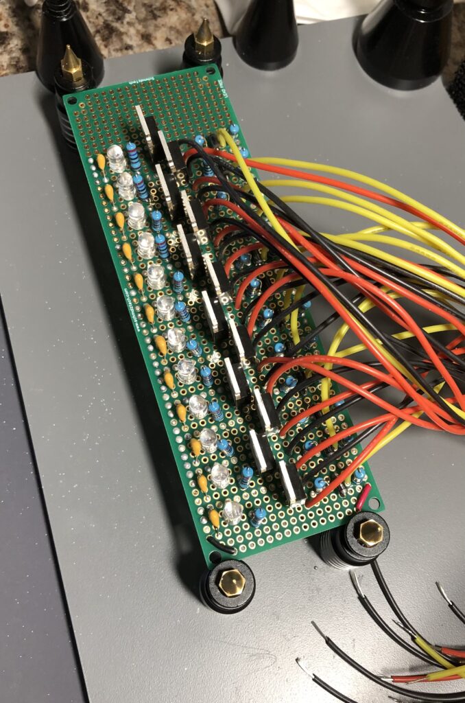
Another strange thing that happened was all of the vehicle states had to be read upside down because yours truly wired the LEDs backwards. The last weird thing that I remember happening was that two of the valves appeared to be flipped however the issue ended up being that somebody had swapped the pneumatic tubing on the static fire test stand.
Something unfortunate was that the latch circuits did not work the way that I had planned, and I attribute this to not using a correctly sized pull-down resistor. Initially I used a 1 mega ohm resistor for the input pins from the switch box. To illustrate just how little I knew about what I was doing I also had used them on the pins going from the Teensy 4.1 to the other input pin (I did not know that the Teensy 4.1 had internal pull-down resistors for the GPIO pins). This had the unfortunate result of both main valves opening as soon as you powered on the system if you had the jumper attached to the pins for the latch. There were more problems. Even if you had no bridge between the jumper pins there was one valve that would always turn on during start up (if I remember correctly it was the HPO channel responsible for the Fuel Dome Regulator).
*****
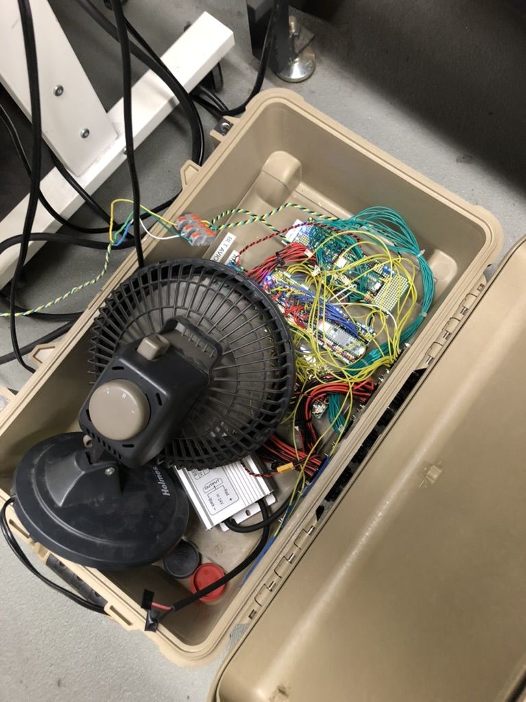
The dry run was on a Saturday and the following day we were supposed to have a water flow test. This presented a problem because in the past BLT avionics had covered the avionics box that housed the ALARA pcbs with a combination of trash bags and duct tape to keep them safe from any mist during testing. If you recall from earlier the fix that was keeping ARALA v2 alive in the first place involved keeping the top of the EGSE container popped open, and also keeping a box fan on it. I reluctantly added trash bags and duct tape, and kind of quietly hoped that if it were kept in the shade that we would not have any problems.
There were plenty of problems that day, and not all of them were avionics related. All told I think we spent maybe 20 minutes debugging avionics between 10AM and 4PM. We had been told by our Chief Engineer not to go past 4PM. Everyone who was there had been working hard between Friday and Sunday.
When I popped the trash bags off to check on the ARALA v2 it felt like an oven on the inside. It was still on, however the LED indicators for almost every HPO channel were glowing brightly. This was not good. I asked if we were done for the day and was told that yes, we were done for the day. “Do we need to use this for anything else?” I asked referring to the ARALA. Our fluids team said that they still needed to purge some parts of the system to clear any water out. After I explained the situation they said that this could be done manually using a K Bottle.
At the time I can remember feeling very unlucky. Most of all I felt bad for our Fluids and Propulsion team because I felt like I had let them down. It was especially embarrassing because we had used a switching regulator on the first version of ARALA, but I had changed that part of the design in an effort to make things more simple. However, this was actually very fortunate and a blessing in disguise because it led to me figuring out the problem that had plagued the HPO channels of the ALARA to begin with. I would consider that my best technical achievement and I have detailed it in the next article on “Chief”.
*****
I ended up fixing the issue with the HPO channel that was misbehaving by pulling down the signal from the switch box within the switch box. I did not really want to mess with any additional soldering or desoldering on the perfboard that had the OR gates on it. It was already crowded and I knew that there was a really good chance of making a mistake. I used 10k ohm resistors for this. However, the correct thing to do would have been to remake the OR gate section, and place the pull-down resistors their instead of solely within the switch box. If there was ever a disconnection, and the only means of pulling the signal down was on the switch box side, then the OR gate could float high and actuate a high power object that should be off.
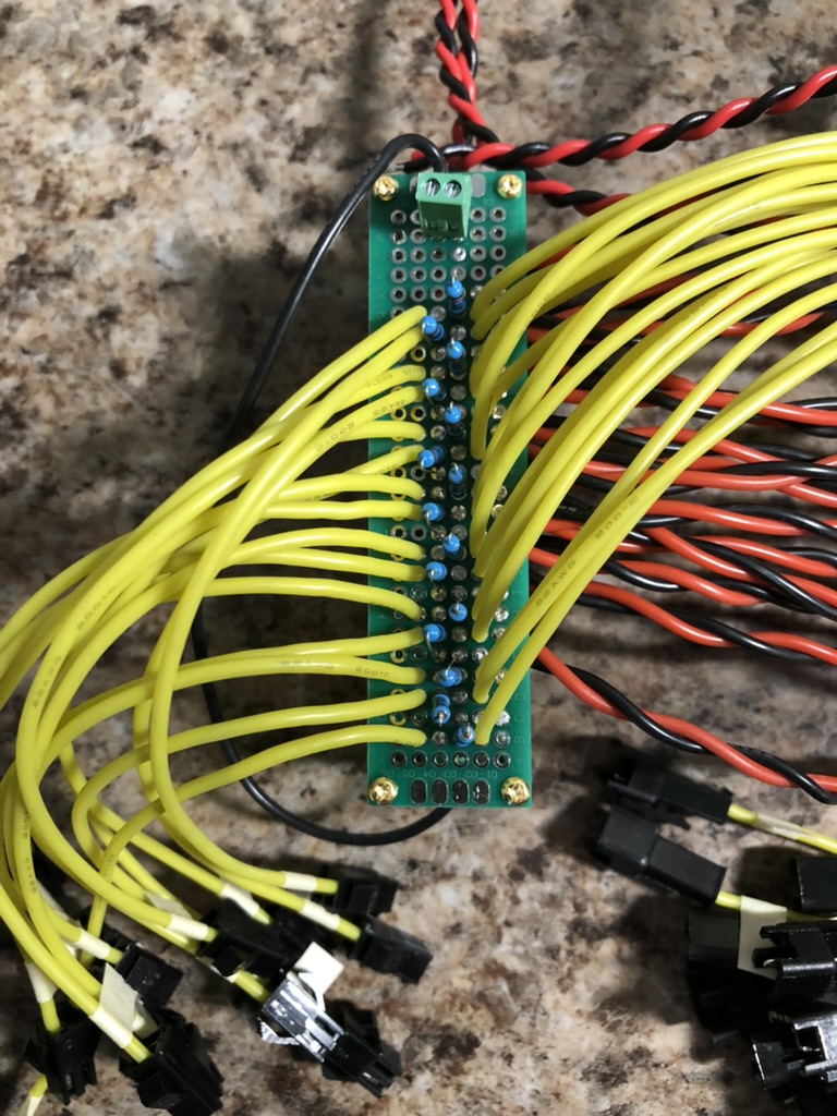
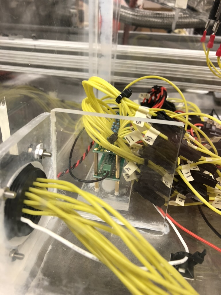
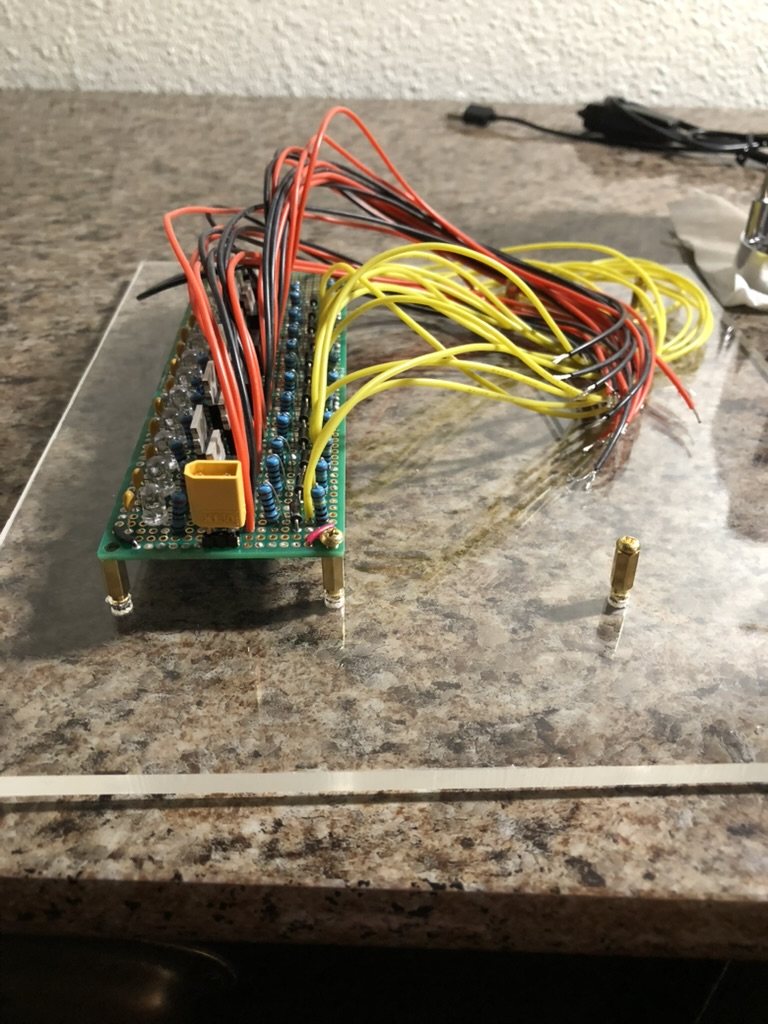
One of the final things that I changed was within the EGSE container itself. I did more JST-SM harnessing so that a user could quickly swap out the ARALA in place of the existing relays without having to undo all of the screw terminals. This was motivated primarily by my experience with the June static fire where we ran out of time messing around with harnessing. That could not happen again. Each relay had five corresponding screw terminals that needed to be done correctly. In our case there were 12 HPO channels. Meaning that if you were in a hurry you had the opportunity to mess up sixty times.
Resources:
1.) ARALA Documentation:
Back to top