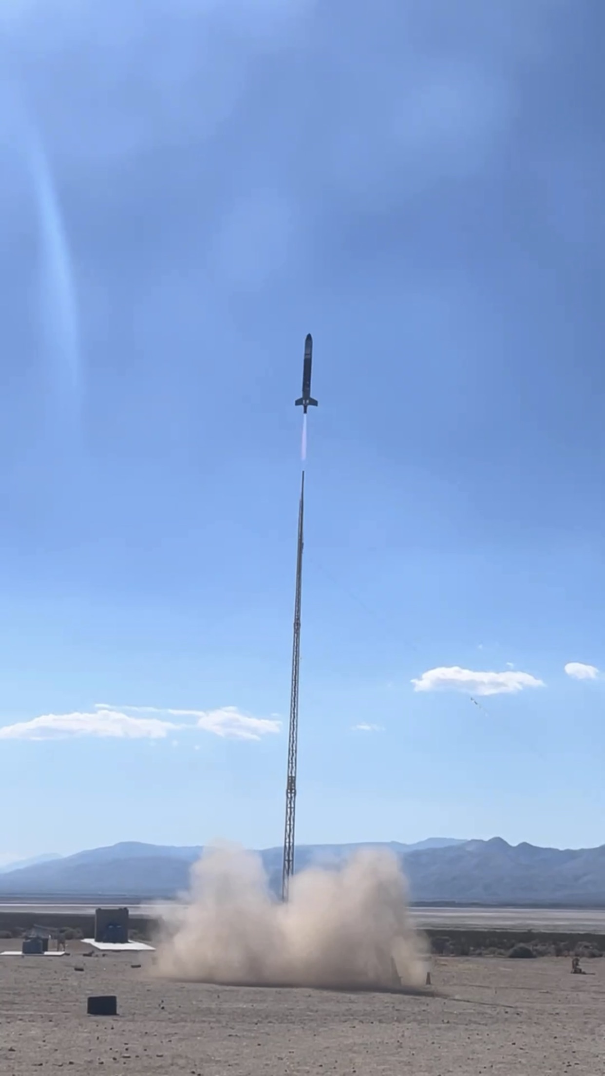
MicroG – K-101 Liquid Propellant Rocket
Code:
* A lot of the code for this project was really just us learning how to use USART and ADC channels on STM32s. We learned a lot but I am reluctant to post any files here because we never really succeeded in getting either of those things to work consistently.
Date:
June ’24 – September 21, 2024
Why:
There was work that needed to be done on the avionics system for the K-101 rocket for MicroG.
What:
After that meeting I described at the end of the CAN article, John Garvey mentioned that he would be building a liquid propellant rocket in the near future, and he told us that if anyone was interested to give him our name and phone number before he left. Within about a week I received a group text detailing a working party that he would be hosting at his house.
A lot of the work involved harnessing. One of the first things that we did was cut a 1,000’ spool of cable into thirds and then attach them to each other to form a 333’ cable. Next, we did a lot of harnessing. Instead of using the Deutsch connectors that I was familiar with from school we ended up using Molex connectors because that was what was available. We also used circular AMP bulkhead connectors – something that I would incorporate into the EGSE containers for BLT and then later ESRA as well. Both of those designs benefited from the experience of this project.
Garv had a metal box in his garage that ended up becoming the switch box for this project. The toggle switches that he had were SPST and SPDT (Single Pole Single Throw and Single Pole Double Throw). These were rated for 20A and 125V AC. Our system was 24V DC and I believe the valves that we used drew ~300mA.
For this design we would use a 24V power supply. However, there were also 9V batteries that we connected in series to use as a back up. I found some T-Type 9V Buckle connectors for the batteries on Amazon, spliced them together, and added butt connectors with a heat gun just to be safe. For Garv’s design we would run 24V directly from the bunker to the high power objects on the vehicle.
Next we needed to add pressure transducers (PTs). If I recall correctly there was originally going to be four however this number was later reduced to 3 (one for each tank and one for the pneumatics section.) Fun fact: the static fire test stand at school at the time used 14 PTs. I knew a little about PTs from doing the CAN code, and I had looked at their documentation page within our build book for the Theseus vehicle plenty of times. However, instead of choosing a three wire PT with a max output voltage of 4.5V, and then having to put that through a voltage divider, I thought that we could save some time by choosing the differential pair version of the model that had an output voltage range of 0 – 100mV. This was such a big mistake it is hilarious! I thought to myself, “Hey, we can save like $40 AND avoid additional circuitry.” Hah!
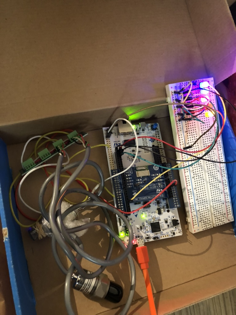
Garv had a unit at home that was basically an early version of a LabJack, but one thing that was really cool is that he allowed us freedom to experiment with other solutions. I can remember for this project we picked out a NUCLEO-H7. One thing he wanted to work towards was wireless communication and he knew that you would need a microcontroller for that. I ended up spending a lot of time on the Cube IDE just trying to figure out how everything worked. The H7 ended up being a poor choice just because of how much stuff is on it. What I mean is that we ended up not needing or using the vast majority of the features on the board.
It would be interesting to go back and try again now, however we never did figure out how to get the differential PTs hooked up directly to the NUCLEO. I can remember looking at the configuration settings and seeing options for differential, but if there is a way to set that up we did not figure it out that summer.
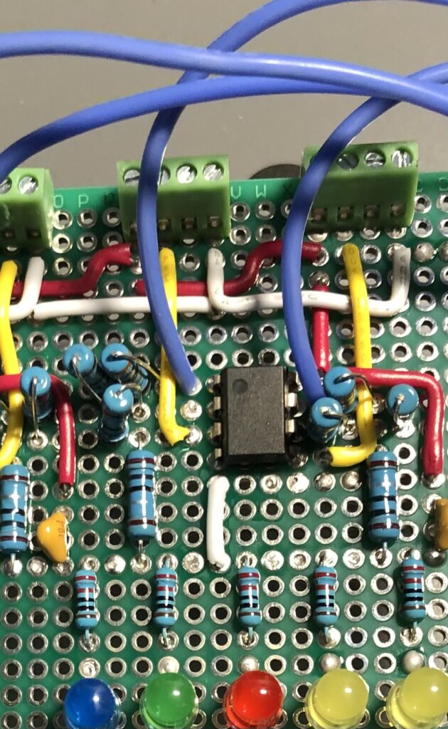
I can remember what we ended up deciding on was to create an operational amplifier circuit. If you’re reading this and thinking, “Surely, he means ‘purchase an instrumentation op amp’ and not create one from scratch,” I have bad news for you. While it was a good learning experience, and looked like it would work when we attached it to an oscilloscope, I had made a mistake with the wiring for the circuit. I was still very new to electronics at this point, and I connected the negative signal wire to the ground pin for powering the PT. Whoops.
I can remember Garv was not impressed. Luckily we were able to get readings using his non-LabJack that I mentioned earlier. (Just to fast forward to launch day briefly – we ended up face time calling an iPhone that was facing the screen of a laptop connected to that device I just described, and then draping a blanket over the top of the setup to reduce screen glare. The phone survived.)
I remember a couple of months later talking to Mark Holthaus at an advisor meeting at school about pressure transducers at school, and he mentioned that he used to use instrumentation op amps on his PTs. Then I looked up “instrumentation op amp” and realized our lives could have been easier. It’s funny to me that one of the motives for choosing the differential PTs was that we could avoid additional circuitry, and then proceeded to try and create an instrumentation op amp.
As part of our effort to figure out wireless communication we ended up going through four different radio modules. I had done some reading and decided that LoRa would be a solid choice. I learned about LoRa initially by studying the schematics for ALARA. ALARA had two options for wireless communication and LoRa was one of them.
The first one was a module called X-NUCLEO-IDS01A5. It plugged in directly to the header pins, and since STM32 has good documentation for their products we figured that it would be easy to use. I can’t remember exactly what was wrong with this module, but I remember we were not able to use it because there was a library that was no longer available.
The second one was a USB module with an antenna called Nooelec RTL-SDR v5 or software defined radio, however this ended up being a lot of work.
For the third one I decided to look on YouTube and find an actual tutorial of somebody with an STM32 device and a LoRa module getting it to work. We ended up getting a SX1278 Ra-02. I watched the first few minutes of a video and remember thinking it looked doable. The individual used something called a Blue Pill and he programmed it using an ST Link. Again, this ended up being a lot of work and between Analicia, the RE from the CAN article, and myself we did not make much progress with it. The idea was that the Blue Pill was simple so we could get it working there first, and then get it working on the H7.
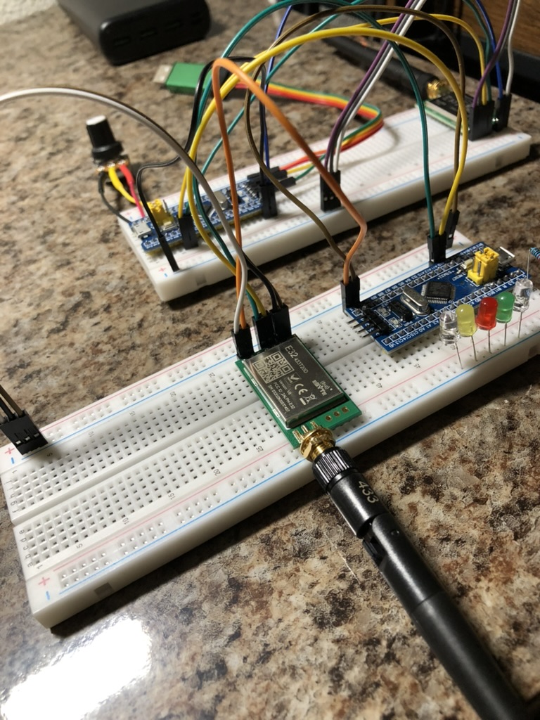
Lastly, I found the UART to LoRa module from EByte and have been using that ever since. I found a tutorial of somebody making LEDs change colors, using a potentiometer as input, and after building it at home on breadboards using Blue Pills decided that this would be the one that we could use. I can remember we were able to get this working on the H7, but we never did get the sensor readings transmitting correctly before launch date.
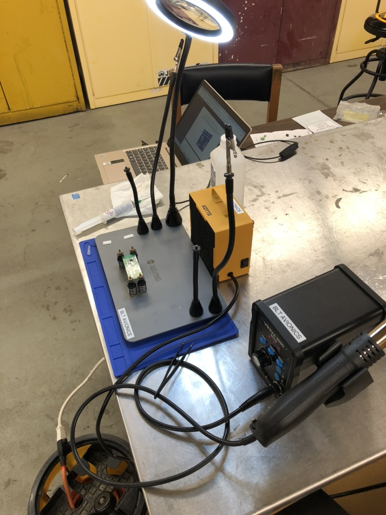
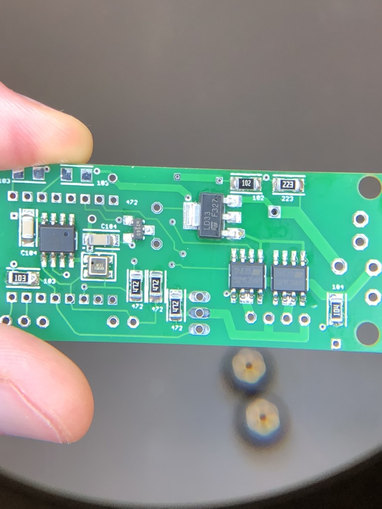
My main contribution to this project was assembling the Quantum Eggtimer. I had a little experience with surface mount components from helping attempt the repair on ALARA 7 from the last article. I had also purchased a reflow station and some kits with LEDs on them to practice before helping with the repair attempt.
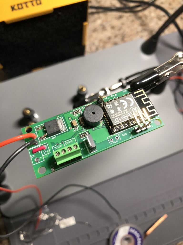
While the Eggtimer worked correctly during a pop test and also during flight, the parachute was wound too tightly, and the vehicle experienced a hard landing.
Around the end of July I ended up shifting my focus from MicroG back toward BLT Avionics. The switch box and EGSE system had existed with a lot of the cutting and drilling finished, but much of the assembly still needed to be done. I only had a rough idea of the second version ARALA and had not done any design work.
I can remember on September 20th I was in the lab finishing up some Avionics work for BLT. I was about to head out but some members from Garv’s project came in with the avionics set up. They were trying to get sensor readings transmitting from the H7 to a new smaller NUCLEO board (evidently they were not fans of the Blue Pill or the ST Link required to program it). I decided to stay and help debug the system. I had not planned on going to the launch, but I ended up being invited after I stayed late to help.
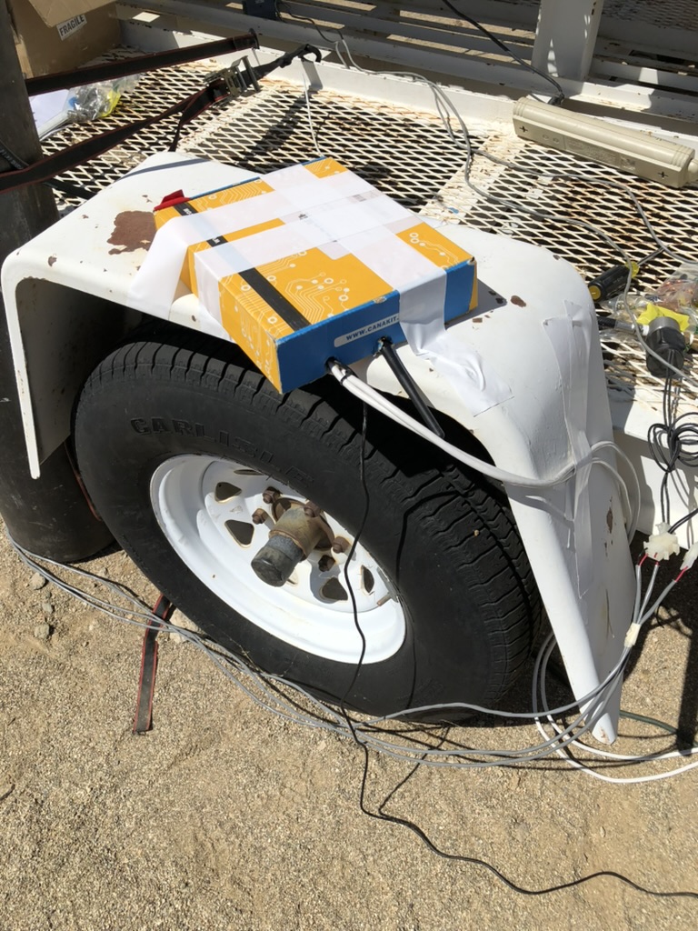
Garv was kind enough to let us try and get the wireless readings working, but it was definitely not a priority. When it was time to launch we packed up our setup, which was housed in a cardboard box, and removed it from the pad. I ended up helping with the “quick disconnect” by removing the sleeve from the amp circular connector that would ordinarily screw onto the bulkhead connector. However this time it was inserted and then taped in place so that it would not fall out until it was meant to when the rocket left the pad.
*****
I can’t overstate how lucky I consider myself to be for having had the opportunity to help out with this project. For one, the timing could not have been better. Since ALARA was retired, and I was going to be the Avionics Lead for the ’24-’25 school year, I would need to build a replacement. This was a really good introduction to see how to make that hardwired, robust, simple system that was mentioned in the last article.
Second, probably the most important lesson from this experience was the pace of the project. I got to see what the pace of a successful amateur liquid propellant project looked like, and the amount of work that is required to actually pull a launch off. Hitting a road block working with someone who has a ton of experience and has all the answers is not a big deal. Hitting a road block with a team of 40 people who are inexperienced could set you back weeks.
Third, this was great exposure to an MVP (Minimum Viable Product). This experience would become valuable later on for identifying things that were strictly necessary (actuating HPOs and getting sensor readings) and things that would be nice to have but were not crucial.
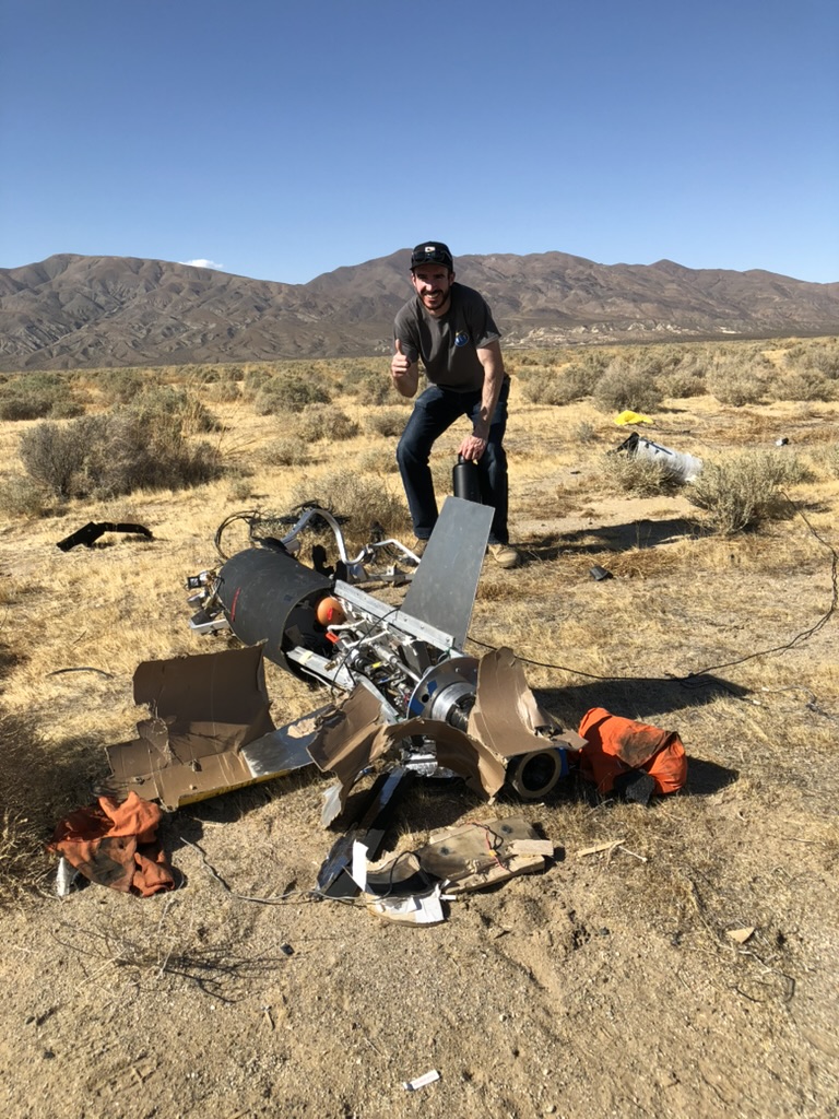
not open up and K-101 experienced a hard landing.