Beach Launch Team – Controller Area Network (CAN)
Code:
Date:
October ’23 – June ‘24
Why:
The code used by the flight computer for Beach Launch Team (BLT) was being refactored, and nobody knew how the CAN software worked.
What:
This project is different from the other projects that I have mentioned so far for two big reasons: 1.) There were other people involved in – instead of just me screwing around in my studio apartment, and 2.) This is the first project that I put 1,000+ hours into.
In order to fully appreciate what all was done will require some context. I decided to go to a meeting for the only liquid propellant rocket team on campus shortly after I arrived at Cal State Long Beach in the Fall of 2023. I started going to avionics meetings and eventually I hung around long enough to where I was trusted with small things. The very first thing I worked on was some harnessing for Deutsch connectors.
Not long after that I heard that the software for the flight computer that the club used was going to be refactored. One day I was in the lab and the current avionics lead mentioned that there was a refactor meeting going on in an adjacent room, and that if I went in and was a fly on the wall that probably no one would care. Probably like a week after that first meeting we started having weekly refactor meetings.
The first few meetings were interesting because some members had been around for a while, and were invested in the old software that was currently being used by the flight computer (called ALARA – All-Purpose Logical Active Rocketry Avionics). We decided that to be fair we should go through each file, about 80 total, and figure out “inputs, outputs, and behavior.” Really what this meant was finding any library dependencies, what other files depended on this file, and then what it even did. Now would be a good time to mention that there was zero documentation written for that software called “RocketDriver3,” and the individual who had worked on it had graduated. If you wanted to communicate with them then it was over Discord.
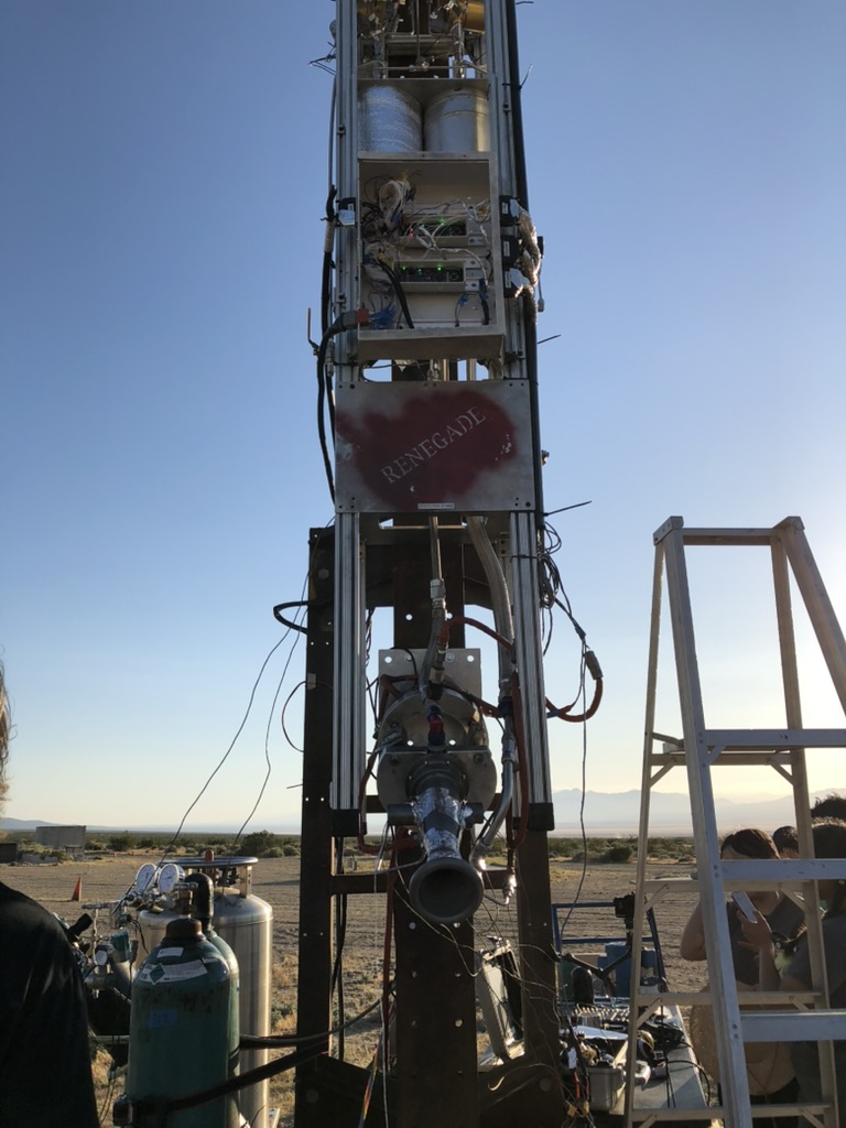
The rest of that Fall semester was uneventful in terms of software development. One thing that did happen in November is that the team blew up the LR101 rocket engine that was going to be used on the launch vehicle. The idea at the time was that the valve timings for the fire sequence had been added incorrectly, which caused the fuel (kerosene) valve to open first, and led to a hard start. This led to a decision later on that setting the times for the fire sequence should be done from the GUI. I mention this because I think it is probably the coolest feature within the CAN software that I wrote.
We had a meeting over winter break on Discord where we went over what all we had found so far, and what documentation we had produced for the existing software. We made a group decision that it would be easier to rewrite the software than to try and refactor it. I don’t think anyone involved in that meeting knew how much work that would prove to be.
Regardless, when Spring semester began and we started to have actual design meetings, I was asked if I would be interested in working with one of the responsible engineers to write the CAN software. I had shown interest in the CAN software before this by intentionally choosing the CANRead, CANWrite, and FlexCANController files. It seemed really important and even more so because anytime I asked senior members about it the readily admitted that no one was exactly sure how it all worked. It was also interesting to me because shortly after beginning the work I found entire organizations devoted to the protocol (CiA – CAN in Automation).
These conversations with senior members were really important, and the CAN software would not have turned out as good as they had if I had not become annoying and started pestering people. I wanted to know what did this system actually depend on. The system seemed complicated, and it was for sure – the FlexCANController file was almost a thousand lines long, but I began to have a feeling that it did not need to be.
I spent a lot of time going through whatever old resources I could find on Discord like unlisted YouTube videos. I watched, rewatched, and took notes on videos that Dan Morgan, the creator of RocketDriver3, made where he discusses how the CAN bus worked at the time. After learning more about CAN, and comparing that to what was in the existing code, I started to see room for improvement.
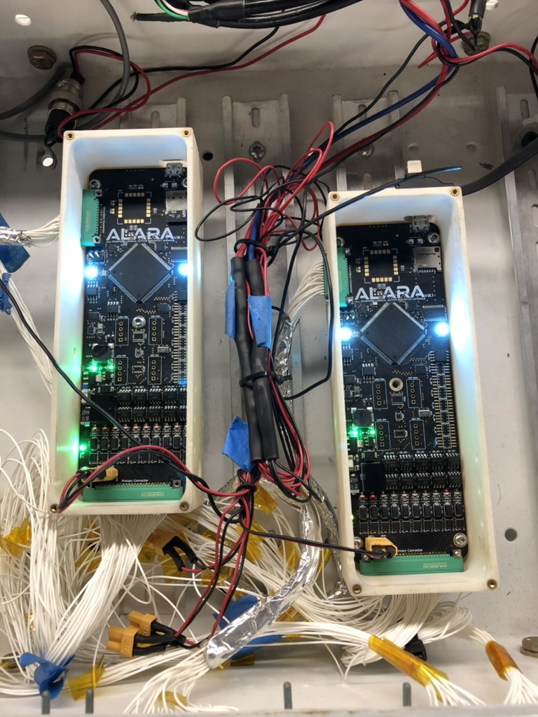
One glaring issue was both the existence and use of a time stamp within that original code. It did not make sense to me why we were taking the time from one ALARA, treating it as though it were the same time on the other ALARA (even though they had not been synched), and then not accounting for the time that it would take to transmit through 400 ft of cable, reach the transceiver, be unpacked by the CAN Controller, and lastly retrieved by the software responsible for the GUI on the Raspberry Pi. A couple of notes: There were two ALARA’s one called “Prop” which was mainly responsible for “upper fluids” like pressurizing a COPV, and one called “Engine” which was mainly responsible for “lower fluids” like opening main valves and starting the igniters.
The way the time stamp was originally used was in an extended id field. The thought process was that since the time would only increase that this was a safe move. This was an unconventional application of the extended ID field to say the least. The first question I had for the group was, “What is this used for?” The answer was that it was not being used for anything. It could be used for data analysis – for instance when looking at the SD cards for the November static fire – they gave you a rough idea of when things happened. However, my thought was that they really didn’t belong in the CAN frame. The way I explained it at the time, and I still think it is a good analogy, is if you were going to tell somebody that you were going to throw a ball, and the person you’re throwing the ball to can’t do anything with it until they receive it – then it really does them no good to tell them, “Hey, I’m going to throw it at this time.” The way it was being used, to me, sounded like a waste of space in the CAN frame.
If the times needed to be synched maybe we could try and do it with the time from the clock on the CAN Bus (sounds hard), or alternatively – if it is the case that we do need this time stamp maybe just add it once the CAN frame arrives on the GUI end (sounds easy).
Next, I wanted to know how much space do we actually need for sensor readings. We had 8 bytes that were usable within the CAN frame, and if we could get four sensor readings per frame (using 16 bits), then that would be ideal. This is what we ended up doing too, but I can remember asking our fluids lead questions like, “Is a negative pressure reading something that we need to worry about?”
Finally, a pattern was starting to emerge. It was not one that I came up with but one that was present (kind of) in the original RocketDriver3 code: we needed to be able to send commands, and receive system reports. By system report I mean the state of the vehicle itself, the state of all igniters and valves (HPOs or High Powered Objects), and sensor readings. There should also be some form of a confirmation message so that all parts of the system are on the same page. That’s easy for turning on an HPO, you just look at the state report. What about for setting a time for burp firing the system though? You need something more explicit like a transmission back from the test stand saying, “Yes, I got that time and it is ___.”
Initially I wanted for the CAN software on the flight computer side to only ever take the CAN ID’s and perform some action with them. Initially, before the design requirement involving timings was added, there would have been no need for the flight computer to read from the data field. It was nice too because I imagined that someone else on the software team might have an array of behavior for the rocket, and they could just take the CAN ID and index into an array in constant time (the behavior for the rocket ended up not being implemented in this way).
I was communicating with the software team responsible for the GUI almost everyday. The GUI team was doing an actual refactor, whereas the team I was in was doing more of a rewrite. If we made a change on our end, but there was no way to leverage it on the GUI side, then it may as well have not existed at all.
*****
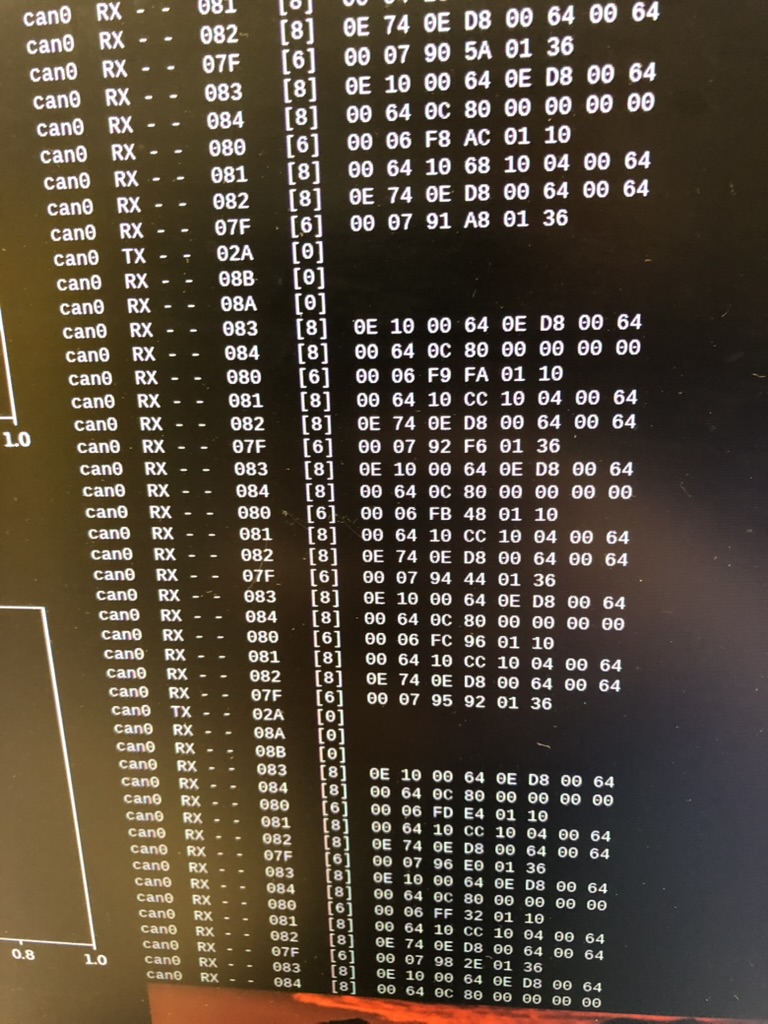
Eventually we got to the point where we were able test CAN. Originally, we were going to test CAN FD as well. However, with the addition of new system requirements that became less and less important. Still, the thought of the CAN routine being reduced to one large message detailing all sensor readings was exciting to me.
I was not familiar enough with the code for the GUI – so I wrote a small python program to help with the test. On the day of the test I remember I was in the lab for probably 12 hours straight. I wanted it to work so bad. I skipped my 5PM class that day. There were a bunch of little things that came up. For instance, I didn’t know that you needed to run a .sh file to set the CAN bus up (I found it eventually). Around 10PM I told our project manager that I think we needed to call it a day. I asked our safety officer if we could extend my test window by one day, and she allowed that.
I can remember coming in Thursday, making a few changes, and it worked! I have a file that I maintained during that time that I will include at the bottom of this article. The main problem, among others, was that the test program I wrote was running so fast that it was spamming the CAN bus and no response could ever be received.
*****
One of the final things that ended up becoming a design requirement was an auto-vent feature. Without getting too into it about a month before our static fire the club decided to add a feature where, in addition to the physical fail safes present on the static fire test stands, there would also be failsafes at a software level. The idea was that if the stand had not received a message from the GUI for more than ten minutes then the system would vent automatically.
I can remember talking to the responsible engineer that I was working with on the CAN code, and telling them that I was not sure how I felt about that feature, but that I would add it if it was really important. Evidently it was really important, and so we created some new CAN frames to facilitate “pings” as part of the CAN communication routine. On the GUI side they created a clock that reset every time both pings (from the Prop. node and Engine node) were received on the GUI end. Joe, one of the members on the GUI team, added colors to the times so that it started out as green while the clock was at 0 and then slowly progressed to a red color after about 20 seconds. The whole ping system ended up being really cool and we never had any issues with it.
Another thing that came up during that meeting was adding in times. I can remember the only way I was able to figure this out was using some global variables that were shared between the two files. This was a very last minute addition but we made it happen. We decided that we would go back later when we had spare time to see if we could figure out a better way to set the timings but I don’t think that ever happened.
*****
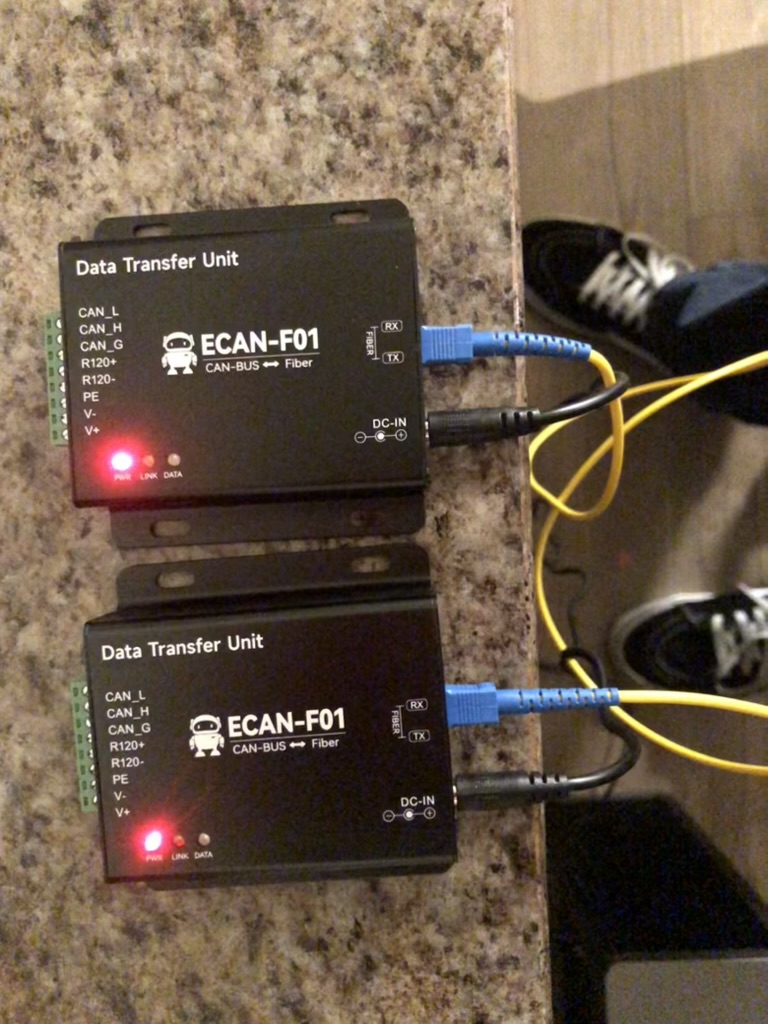
Before heading out to the test site we needed to extend the length of the data cable (the CAN bus). I can’t remember exactly why the cable needed to be extended, but I believe it had to do with a pad that the club had used in the past being unavailable for our test date. That and I can remember we needed a longer cable for launch anyway. However, when we extended the cable the CAN bus stopped working completely.
This was the night before heading out to FAR and it was starting to get late. I asked if they could plug the old cable back in. They did and it worked. We tested continuity on the new cable, and then I remembered something I had read about cable length: we needed to reduce the baud rate. Originally it was set to 500,000 bits per second however with the increased length we needed to reduced it to 250,000 bits per second both on the .sh file and within our code for both ALARAs.
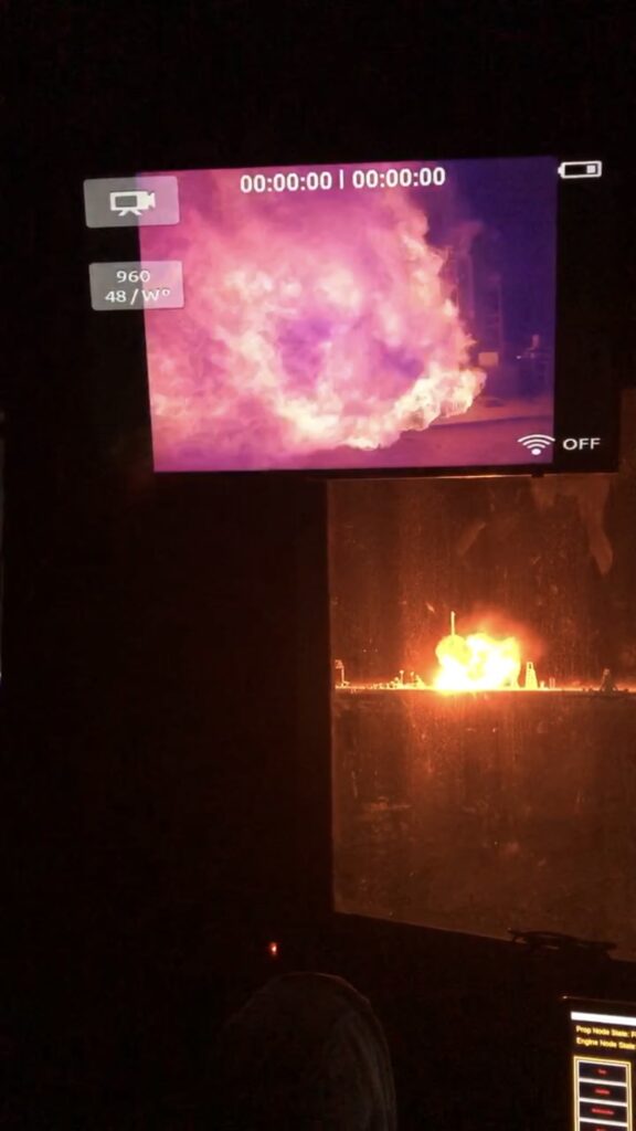
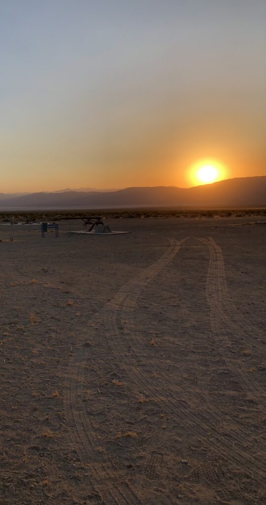
Next, we went out to FAR for our April 20th static fire. We ended up having another hard start, however the system behaved perfectly from a software perspective. The timings were set so that instead of firing for a whole 5 seconds, they would go for a shorted time period, or a “burp”. This was good because it resulted in a smaller explosion. While there was clearly a lot of work to be done I think that everyone was really happy with how the software we wrote turned out. Our code ended up being called HRC short for “Heraclitus Rocket Controller.” This was because the launch vehicle was called “Theseus”. I was not involved in the naming and whenever anyone asks about it I say, “It’s all Greek to me.”
What ended up happening next was a combination of cold flow and water flow tests that were done at the Compton airport. Unfortunately, around this same time the ALARA flight computers started to fail. Specifically the HPO channels responsible for actuating valves and igniters. We noticed some bad behavior during the April static fire during setup. One of the LEDs for an igniter channel was indicating that the channel was on even though it was off. This was noted, and was not a huge deal because we had two igniter channels, but it was foreshadowing more issues to come.
The engine node was the ALARA that was experiencing problems. The prop node was fine for now. However, because the two work as a team we needed to figure something out. We were supposed to head out to FAR again in June to see if the data we collected from the water flows would prove useful in successfully firing the LR101 that had now been blown up twice.
The first thought was to create another ALARA. The creator of the ALARA, Brandon Summers, had graduated but he was available on Discord for some questions. Our best shot was an ALARA that had been mostly assembled but still needed a couple of things. We were also trying to fix the engine node, but were having issues with the circuitry for the HPO channels. These channels used a combination of MOSFETs and Optocouplers in order to turn the channels on. This redundancy was a safety feature.
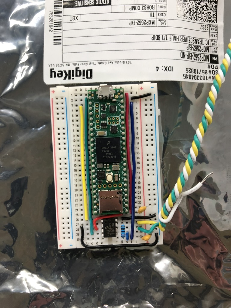
We were unsuccessful in definitively diagnosing the problems the engine node was experiencing. We also succeeded in releasing the black smoke from the ALARA that had been mostly built but refused to turn on. I had suggested earlier that we should maybe see if we could put something together with a Teensy. The ALARA was basically a large Teensy 3.6 with sensors for flight that we were not using, and also the 24V HPO circuitry. You could no longer buy Teensy 3.6s, but I had been messing around with Teensy 4.0s and 4.1s at home.
Around the time the black smoke was released from what would have been ALARA 8 (6 was the prop node and 7 was the engine node) I showed a video of me actuating a cheap 24V solenoid valve using a boost converter and a Teensy. This was the second time pitching the idea, but it was well received this time.
I have a whole other article on the development of that device which we decided to call ARALA (ALARA backwards). The only reason I bring this up here is because we needed to make some changes to the CAN code. The libraries that are used for the Teensy 3.6 processor could not be used on the Teensy 4.1. There is a version “A” on GitHub where the changes for HRC were made for the ARALA.
June came and went. Unfortunately, throwing ARALA together at the last minute proved to be more work than we were expecting, and it was not ready for static fire testing.
What happened next is a little sad but it needed to happen. After a meeting with our advisor Dr. Yoozbashizadeh, Mark Holthaus, and John Garvey, we decided, collectively that ALARA needed to be retired, and that we needed to focus on making things more simple first. The instructions that I was given was to create “a hardwired robust system,” and to “go for the easy thing first, and then build from there.”
I think that everyone was relieved. However, I still think that I am beyond lucky to have worked on something like ALARA. It wasn’t just working on it, I was given the opportunity to build a new communications software for the existing network using CAN, which was awesome.
I didn’t just learn a lot about CAN, but I learned a lot about everything that it touched as well. By the end of the project I had a pretty good idea of where a lot of the sensors and valves where on the test stand. It is hard to remain ignorant of something like a pressure transducer or a solenoid valve when you see how central they are to a vehicle doing exactly what it needs to do.
I think of where I was, literally copying down existing code by hand, and thinking to myself, “There is a good chance I am never going to figure this out,” to things slowly clicking into place over the span of months. It was also great from a hardware perspective because of how simple the circuit is for the CAN transceiver. It is all passive components, an IC, and traces to the appropriate pins. It was just challenging enough to be rewarding without feeling too far out of reach.
I am very thankful for Brandon Summers, who created ALARA, Dan Morgan, who wrote RocketDriver3, and Analicia, the responsible engineer who asked me if I wanted to work on the CAN code. Oh, and Pawlesky and Tonton81 for the Teensy 3.6/4.x CAN libraries (whoever and wherever you are).
Resources:
1.) Here is a link to the original RocketDriver3 CAN code that I was tasked with rewriting:
2.) Initial Presentation I gave for rewriting CAN code:
3.) Testing Sheet so that everyone knew what was going on:
4.) CAN Test Report:
5.) Partial ALARA Documentation:
6.) Scan of my CAN notes*:
* There are some notes in here that are not strictly related to CAN, but were used to help me understand some of the terms on the ALARA schematics.
Back to top