Segmented Mirror
Code:
No code for this project.
Date:
Summer 2022 – Summer 2023
Why:
I wanted to see if I could create a device capable of focusing sunlight and producing high temperatures (~900 C) using cheap materials.
What:
I was looking online to see if there was a way to release CO2 from calcium carbonate for an unrelated project. I found some “solar concentrators” on Amazon that would have worked. Unfortunately, these concentrators were out of my price range.
I figured that probably many people had attempted to create solar furnaces, and that there was likely a lot of good information online. I found many DIY videos/articles. A lot of them involved using some combination of mylar and fiberglass resin. Others involved putting mylar over a hollow cylinder, and then temporarily evacuating air from the cylinder with a vacuum to produce the desired effect. I also found some awesome videos on hydroforming using grease guns. My goal was to keep the project as inexpensive as possible so this would not have worked for me.
A common theme in most of the videos, excluding those on DIY hydroforming, was a lack of technical information. Like in my case, I had a very specific temperature range that I was trying to achieve, and so far, I had not found anything on how to go about creating something based on that. A lot of the videos would show the reflector being built, and then cut to something being burnt with it. Another thing that was unsettling to me was that none of the videos/articles I came across involved segmented mirrors. Why had nobody done a DIY video on this?
I decided to create my own design. My first step was to use a tool on Desmos to get an idea of how to segment a parabola: how could I approximate a curve using straight edges? It is worth noting here that in industrial applications the mirror segments that are used do have some curvature to them. They are not flat. In my project they are flat, and as you will soon see, that proved to be enough of a challenge for me.
The equation for the parabola depends on how high you would like the focal point (or “focus”) to be. I knew that the parabola would likely need to be shallow. I also knew that there needed to be a relationship between the surface area of the paraboloid (traced out after the parabola was revolved about an axis – the axis that divides it symmetrically) and the amount of thermal power the reflector can produce.
I found the answers I was looking for on the Stack Exchange for physics. What I found is that under ideal conditions (clear sky, at the equator, at noon) one square meter is capable of producing approximately 1kW. From here I was able to determine my bounds of integration for the surface area integral that I would need to compute.
After I had that down I was set! I would just draw this thing on Fusion360 real quick, print out the template, make my 1:10 replica, scale it up, and I would be separating CO2 from calcium carbonate in like a month … max! Yeah, that did not happen. Not even close.
*****
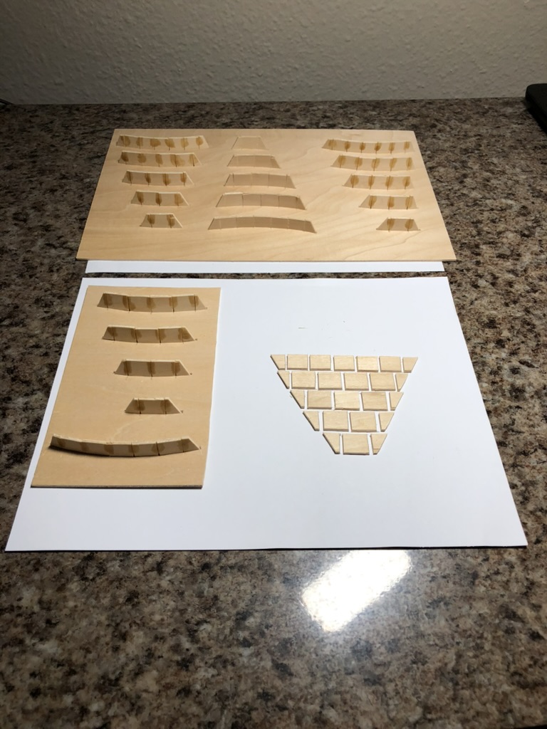
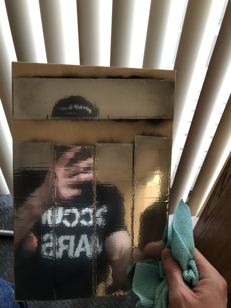
There were quite a few design iterations early on when trying to figure out how to get all the cross sections to fit together. There were 6 frame pieces glued directly on top of a base piece in the first version of this design. I decided that instead of gluing all of the “mirrors” together that it would be best to create some other structure beneath it that the mirrors could be glued onto directly. I called these “cross sections” because they “cross” each section of the mirror. The mirrors were created by attaching inexpensive aluminum tape to a piece of balsa wood, polishing the strips using metal polish and a microfiber towel, placing a template over the strips, and then cutting them out with an X-acto knife.
The first major mistake I made was that I did not account for the thickness of the material in some of my very first drawings. This resulted in the paraboloid’s surface being about 2mm higher than it should have been. I tried reproducing a parabola in Desmos to see if it was just a translational problem (had the entire curve just been shifted up?), however I was not able to produce an equation that fit with translations.
To fix this I recessed the line segments that made up my parabola in Fusion360 by 2mm. When I did this, it changed some things. If you can imagine you have a point where two edges come together – how do you even “recess” something like that in a way that makes sense?
What I did was I selected the point between the two segments and made a line perpendicular to one edge by 2mm and repeated the process for the other edge. Next, I made a projection perpendicular from the line I just created, parallel to the original edge now, in the direction of the other 2mm line I had just created. I repeated the process for the other edge and marked where these two lines intersected. That became the new point between the two rows of cross sections (in my drawings I called these “tiers” and labeled them with roman numerals).
I think that this warrants an explanation because for me, and maybe for you too, it is not very intuitive. I know that at first, I thought, “Oh, okay, just divide the parabola up into straight segments.” What I found though, is because the curvature of the parabola varies at different points then so will the lengths of the segments. The most curved region is near the vertex of the parabola. As we will see shortly this has some very important consequences for the design assuming that you want all of the mirrors to be the same size.
If you were to look at the line segment lengths that were determined by looking at the parabola, and the length segments on the drawing before they are recessed, then you would find that they are different for the reason mentioned above. After you recess them by the width of the material then they will appear to be even more different from the original lengths determined by using the parabola tool on Desmos. This could be confusing if you were anticipating that all the lengths would be the same because all of the mirror lengths are the same.
That was the first major hurdle.
*****
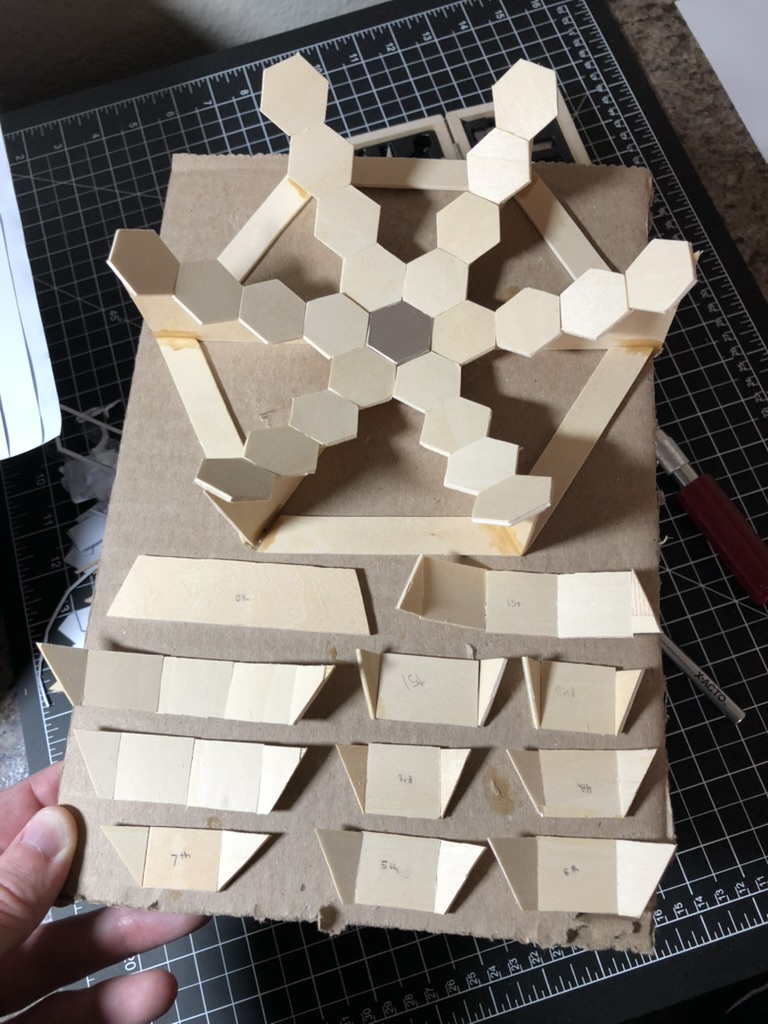
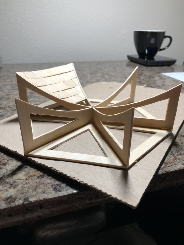
I mentioned the cross sections above earlier. How do you get them all to fit together? Initially I thought that it would be as simple as taking the length of mirror, and cutting rectangular segments so that the mirrors could be glued on top of them. For the cross section pieces that would come into contact with the frame, I made those triangles. That did not work.
To get all the cross sections to fit together I created a template where they could all be placed together, and with a small amount of wood glue, I found that they would stay in position (for the most part) when removed from the template.
What ended up happening is I created about twelve different drawings before I figured out how to get the cross sections meeting with the frame. This is another problem with this design that for me was not very intuitive. I would create a drawing with some minor modification, cut out the template, tape it to balsa wood, cut the pieces using X-acto knives, cut the new template (if the pieces differed enough in length), glue the pieces using the template, and then finally try to see if it would fit between the frames.
I found that to really know if I was doing it correctly, that I should do the tests on tiers with more cross sections. Why? Wouldn’t I want to use a tier with as few pieces as possible to be efficient? That was my approach at first, but what ended up happening is I found myself wondering, “Is this off because of the frame, because of my cuts, or because of the design?” When I worked on tiers with more cross sections I did not have this issue because it was extremely apparent when something was wrong.
There are six individual frame pieces which means that the angle between each frame piece is (ideally) sixty degrees. If, for example, you were in tier II, then there would need to be 3 cross section pieces (1 rectangle and 2 triangles on the ends). This means that there will be 2 “breaks” between the 3 pieces. One thought I had was that the angle between the cross section pieces would simply be sixty divided by 2 in this case. That won’t work here though. That would work for a cylinder. The problem is that each segment has some incline angle to it depending on which tier it is, in addition to the angle that I just described. That combination of angles is what was throwing me off.
To find this angle I reproduced two triangles in Fusion360 that represented the inclined tiers of the frame. Next, I put the angle that I mentioned above between them, in this case 60/2 = 30 degrees. After that, I made an orthogonal projection from the midpoint of each segment. (Note: It did not have to be the midpoint. It could have been the same point anywhere on the two segments. I chose the midpoint out of convenience, because Fusion360 makes it easy to see when the mouse cursor is at a midpoint.) I made the projections long enough to where they would intersect in space – just some relatively huge number like 50cm. Next, I used the measurement tool to determine the angle between the intersecting projections. That is how I was able to determine the angle between the cross sections.
There were a few more little surprises when getting the lengths of the cross sections correct. I do not think that writing them here would be very appropriate as there are a lot of little details. I think an explanation would be better suited for a video. I will mention though that there is a little routine that you need to go through to get the triangular cross section pieces fitting correctly, and if there are many tiers this can take some time.
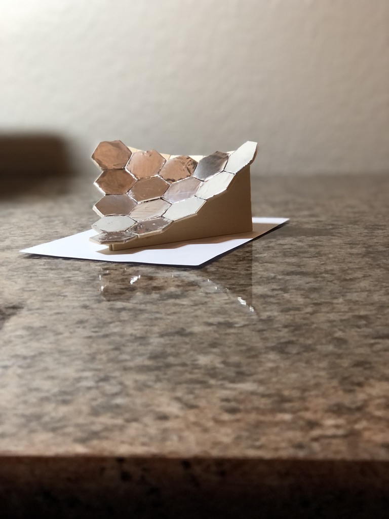
By the time I finally got everything figured out I only had enough building materials to construct one of the six sections of a replica. Fall semester started and I had no time to work on this project. Which was fortunate because there was another big problem with the design that I had not found yet.
*****
The main problem with my first version (the “pizza slice” 1/6th of a paraboloid looking thing) is that I did not consider the wavelength of the sun’s light that I was taking advantage of. It would have worked, but it would have been inefficient. The focal point would have been very large, because I did not account for error tolerance within the design of the segmented mirror.
I learned, from a question asked on Stack Exchange, that this tolerance can be no greater than one fourth of wavelength of the electromagnetic spectrum that the instrument is trying to use. In my case, the design would have to be precise to 2.5mm (one quarter of a centimeter). When I created the line segments to fit the equation of the parabola, I did not account for this. I chose end points based on the desired surface area, and from there divided them up as evenly as possible for my own convenience.
I needed to fix this to have the design working optimally.
I decided that I would need to base the mirror size off the most curved portion of the parabola (near the vertex). I found the length by creating a straight-line tangent to the vertex. I stopped when the curve of the parabola deviated from the straight line by more than 2mm (a safe 0.5mm cushion in case any adjustments needed to be made later). I did the same thing for each tier. Then I compared them all in Excel, and I had to do a little bit of work because, like I mentioned before, the line lengths will not all be the same. I have read where a formal error analysis of segmented mirrors is actually very involved, and my “fix” is probably crude by comparison, but I think for this personal project that this treatment was sufficient.
Building the second version of this design was very smooth by compared to the first version. I had worked out all of the more challenging aspects of the design the first time through. I made some other additions too. I sanded the edges of frame pieces to where they would all meet nicely at a point in the center of the hexagonal base. I created little jigsaw teeth so that I could fit the frame pieces into the base instead of just relying on my eyes and Gorilla Glue. I also cut large sections out of the base and frame to reduce the weight of the mirror.
So, after a year of work on the design the 1:10 model must have been completely devoid of error, right? Hah!
One large source of error was my own craftsmanship. I tried to cut and glue as carefully as I could, but if I was off by a little here and then a little there, then soon things were not fitting together correctly. Another source of error was the wood that I was using. I did not store the balsa wood correctly and unfortunately it did warp a little bit. I also bought the cheapest balsa wood available which may have also been a mistake. I did not think that this would have much of an effect on the model, but looking back on it I should have bought new wood.
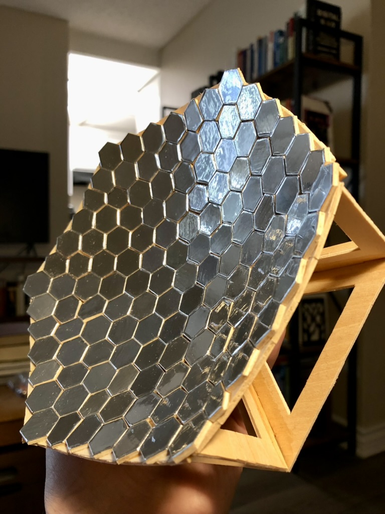
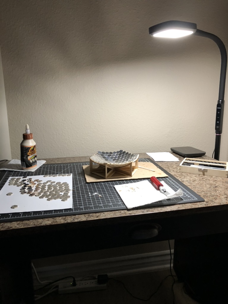
What ended up happening is that some of the mirror pieces did not want to fit in their places on top of the cross sections. When I realized this, I seriously considered scrapping the whole thing and building a new one, but I decided to keep it the way it was. I ended up shaving little slivers from each mirror piece that was giving me trouble. If you were to look at the gif on the homepage long enough, you will see what I am talking about. The size difference in some of the hexagons is very apparent. If I were to repeat the process with a laser cutter, in a well-ventilated area so that I am not inhaling formaldehyde vapors, and wood that was not warped, then things would fit together much better.
I made another mistake with the second version of this design, but this mistake was probably a good thing. This was supposed to be a 1:10 scale replica. I made a careless mistake while calculating one of the lengths on the mirror pieces. Unfortunately, this error propagated throughout the entirety of the design, and the replica is now ~1:8 scale.
This scaling error ended up being a good thing. Even at this ~1:8 scale the pieces were small and at times difficult to work with. For example, on the frame pieces, I needed to mark where one tier ended and another tier began, because the difference in some cases was 3 degrees or so. It would have been difficult to see where to glue the cross sections otherwise. It is difficult to imagine things going more smoothly at a smaller scale.
I have not had time to take the model outside and see how much thermal power it can produce. I have a couple of ideas in mind for measuring that, and I will post them in the future.
This was not a software project, but I think it was a good project for me to work on regardless. I learned a lot about segmented mirrors. Thinking back on it I used concepts from just about every math class I have taken so far (up through multivariable calculus).
I imagine there are easier ways to do this. For instance, I chose to use cross sections because I did not want to worry about getting glue on a mirror, and possibly reducing the power output, but I’m sure there is a less painful way to approach this. I just went with what was most apparent to me at the time.
Another consideration that may affect power output is the edges of the aluminum foil on the mirrors. Plenty of adhesive attached itself to the X-acto knife while making the cuts, and I had to clean the knife frequently. This would sometimes pull the foil up and away from the wooden hexagon that it was supposed to be attached to. I did my best to ensure that the edges stayed as close to the wood as possible, and that they remained pushed down, if anything, and not up. I think that this could cause some loss of power if the edges of the mirrors caused the light to reflect in an unintended way.
A final consideration is the smoothness of the mirrors. I should have sanded the balsa wood for the mirrors a little bit with a fine grain piece of sandpaper. I noticed after I polished the aluminum tape that pushing the foil into the piece of wood caused some grooves in the balsa wood to be exposed. I think that this could be another potential source of inefficiency.
Remember earlier when I mentioned that I wondered why I could not find any DIY projects on solar furnaces with segmented mirrors? Now I know why! I do not regret this. This was not a software project, but it was a cool project. It could easily become an electronics project by implementing a tracking system. That could be an addition for a future project.
Back to top